Over Braid or
Double Shield
Over Braid or
Double Shield
Over Braid or
Double Shield
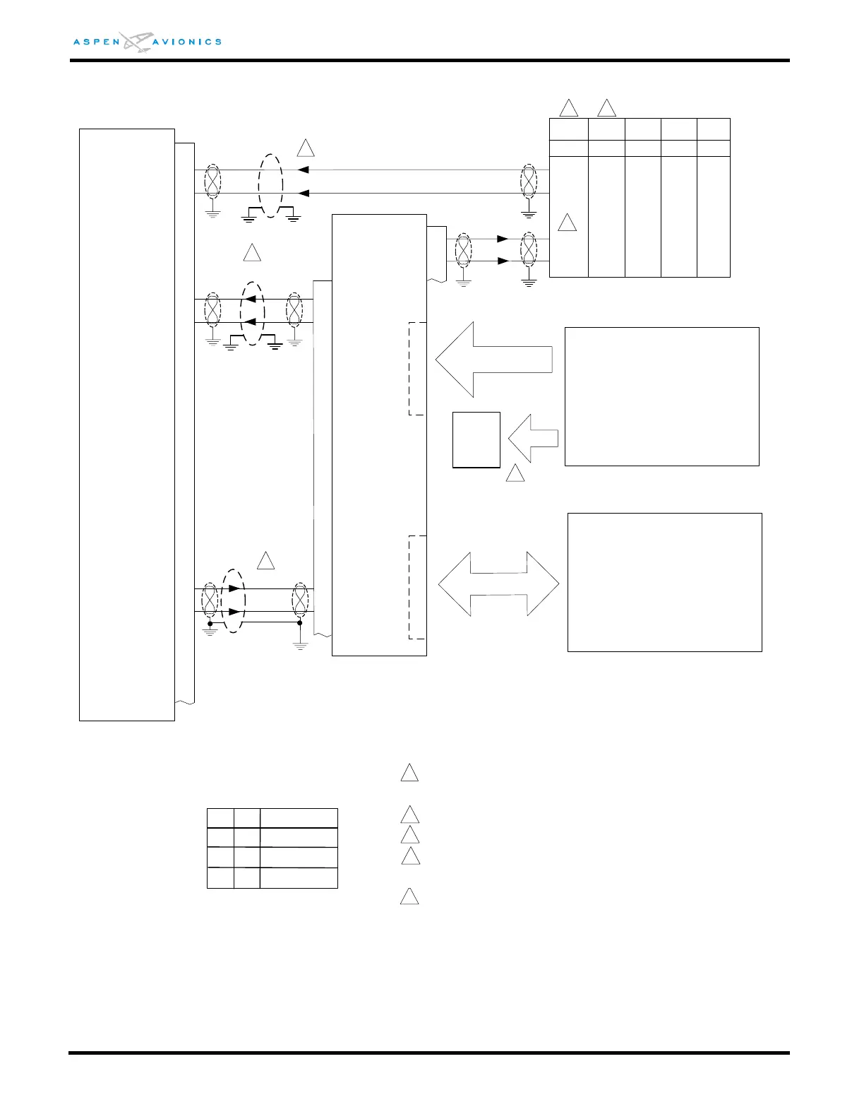
EFD1000
VLOC RX2A
VLOC RX2B
ACU/ACU2
P3
18
19
26
27
14
1
15
2
PFD 429 TX1A
PFD 429 TX1B
Autopilot - optional
429 RX1B
429 RX1A
429 TX1B
429 TX1A
A
U
T
O
P
I
L
O
T
ARINC 429 GPS
Analog VLOC #1
Optional
Back-Up
Nav
Indicator
V
L
O
C
#
1
See Figure 9-24, 9-25, 9-26 for Back-Up NAV
recommendations.
1
2
3
GPS400
GPS500
GTN625
635/725
GNC250XL
300XL
GPS155XL
Px001
P1001
J101
J1
P3
4
5
16
17
GPS RX1A
GPS RX1B
429 TX2A
429 TX2B
16
15
16
33
32
46 10
47 29
48(50)
49(51)
15
67
48
33
32
4
ID#1
Description
D
E
ID#2
NONE
NONE
GPS1, No NAV1,
GPS1,NAV1
5
3
See Figure 9-15 for:
KX-155(A) &165(A)
KN-53
KX-170A/170B/175/175B
SL-30
Use pins 48 & 49 or 50 & 51 not both.
2 2
4
See Figure 9-27 for GNS and GTN configuration.
1
1
1
Over shield or over braid required on this wire
bundle to comply with HIRF & Lightning. Extend
within back shell. Ground at both ends.
Configuration Matrix
(see Section 10)
KLN
90/A/B
P901
24
23
5
4
Refer to manufacturers’ documentation to
verify the integration data and for information
regarding checkout procedures. This drawing,
as it pertains to the non-Aspen equipment, is
for reference only.
See Figure:
9-16 to 9-20 for Autopilot
M*
NONE
No GPS1,NAV1
* The “M” config is only permitted for
Aircraft Limited to VFR.