EFD1000 E5 Dual Electronic Flight Instrument (EFI) Install Manual
DOCUMENT # 900-00041-001 PAGE 186-226 REVISION D
© Copyright 2019 Aspen Avionics Inc.
Aircraft Type: ______________________________________________________ Date: ________________________
Aircraft Serial Number: _____________________________________ Tail Number: ____________________________
The following five pages must be printed and used during checkout. The Section number refers to the
section in the manual where the test is performed. This form must be included in document package to
be included in aircraft maintenance records.
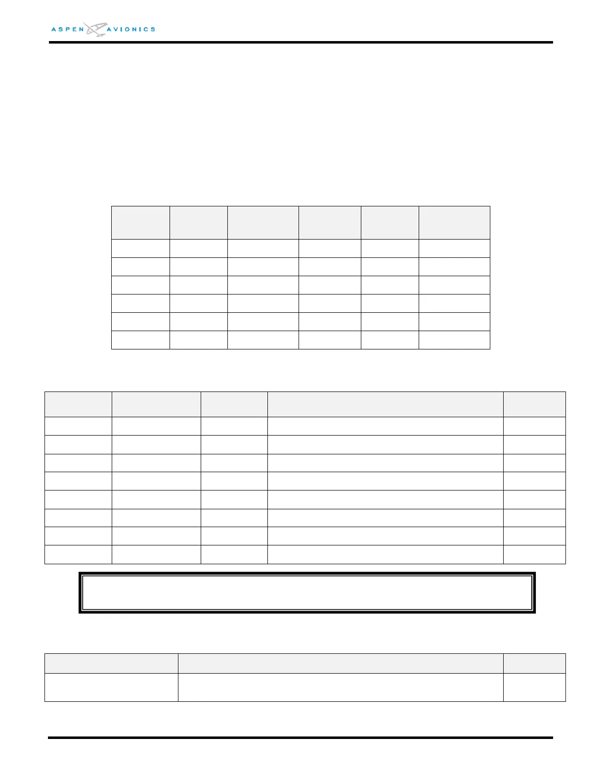
Complete by performing test of Section 10.5.4
Calibrated
Heading
Source
Calibrated
Heading
Source
Complete by performing test of Section 10.6.1
Red arc displayed at all speeds above Vne
Yellow arc extending from Vno to Vne
Green arc extending from Vs to Vno
White triangle at initial flap extension airspeed
Aircraft with Vmo/Mmo Airspeed Indicator
Barber Pole or Redline
Position
Verify the Barber Pole or Redline appears at the correct airspeeds
as shown in Table 10-1.
NOTE
Single engine aircraft and aircraft with no flaps will not use all parameters above.