7. Unit operation
User Manual – PhysioGo.Lite Electro page 34 / 96
7.3.4 Limitations
The list of limitations in the unit operation:
Treatment channel 1
Set electrotherapy mode A+B
Until the treatment in channel 1 is completed and the edit mode is
exited, it will not be possible to select electrotherapy B in channel 2.
Treatment channel 2, selected
electrotherapy B
In channel 1 there is a possibility of setting only electrotherapy A
I/t curve available only for 1 channel electrotherapy A.
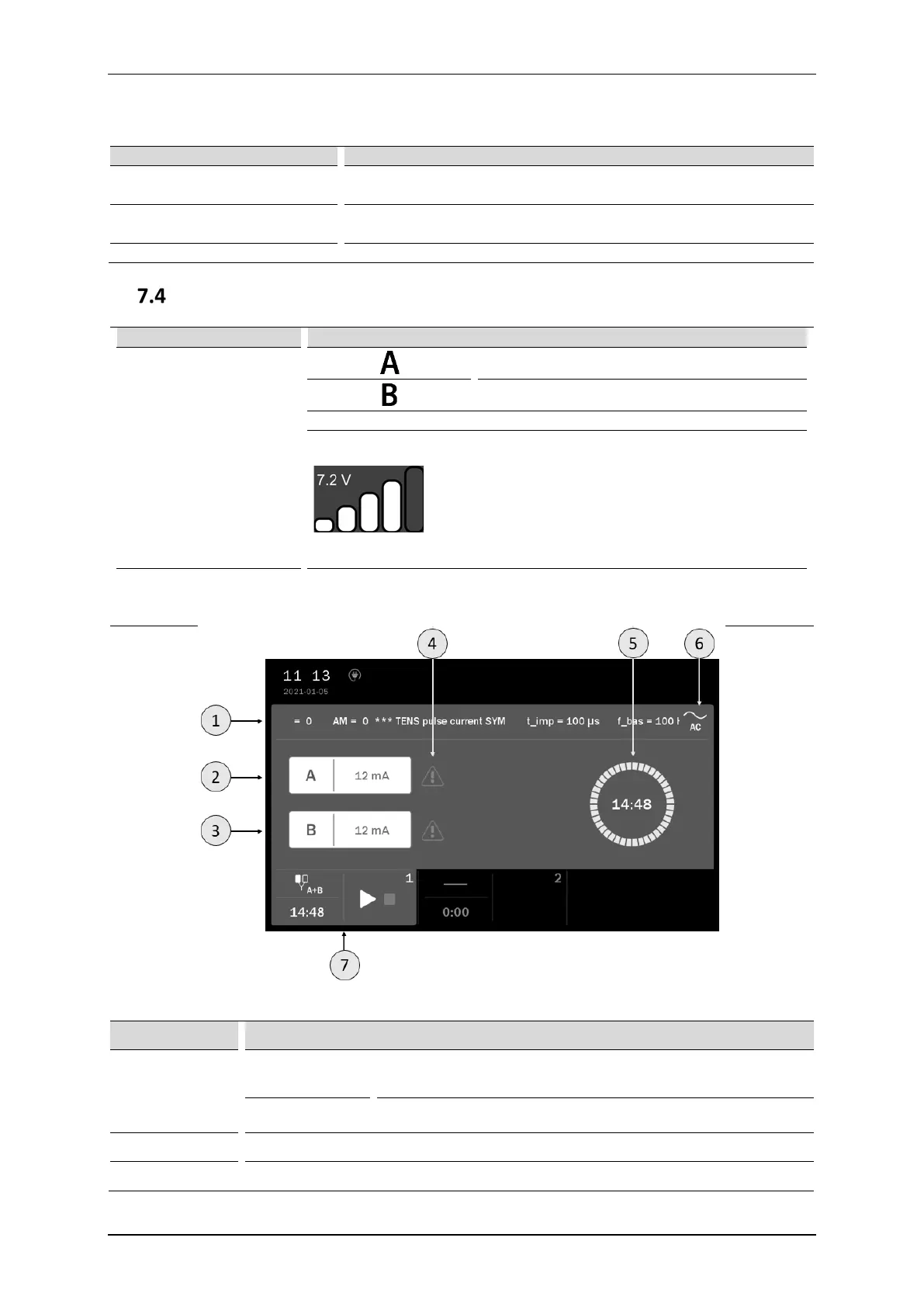
Display description
Output signals of circuits
and amplitude settings
identifiers
Electrotherapy circuit – socket A
Electrotherapy circuit – socket B
Amplitude settings of current and voltage for electrotherapy circuits
CV mode – the voltage value and the estimated intensity
of current flow, where:
• one column – current < 10 mA,
• two columns – current in the range of 10÷20 mA,
• three columns – current in the range of 20÷30 mA,
• four columns – current in the range of 30÷40 mA,
• five columns – current > 40 mA.
Time indication
Presentation of the treatment elapsing time.
Moreover, for electrotherapy sequences, indication of the sequence step.
The indicator of currently executing step is blinking.
Figure 7.2 Screenshot sample view for dual circuit electrotherapy A+B
Symbol Description
1
Manual mode
current name and shortened information on treatment
parameters
Program mode program name
2 A circuit identification and amplitude value
3 B circuit identification and amplitude value