8. Definitions and parameters
page 53 / 96 Issue date 18.05.2021, rev. 1.0
Symbol Description
the treatment
Available parameters
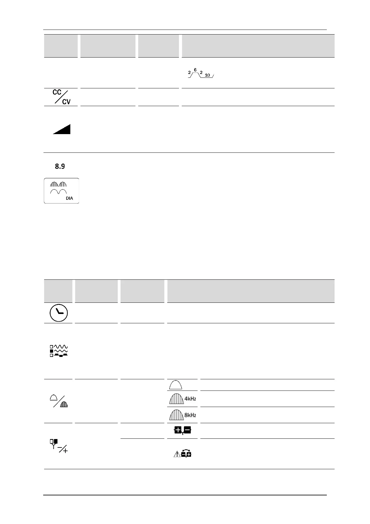
Stimulation phase 6 s
Fall time 2 s
Amplifier operation
mode
-
CC – stabilized output current
CV – stabilized output voltage
Maximum
amplitude
-
Regulation step:
• 0,5 mA in the range of 1-140 mA
2 – 140 V in CV mode, max. 140 mA
Regulation step:
• 0,5 V in the range of 2-140 V
Diadynamic currents
The device generates unipolar low-frequency currents or a medium-frequency carrier currents, whose envelope
corresponds to the traditional diadynamic currents. There are no significant therapeutic differences between
such an approach to diadynamic currents generation and traditional method. However, because of applying
medium frequency current, the unpleasant patient’s sensations during the procedure and the electrochemical
effect are reduced. With this method of signal generation, it should be taken into consideration that a higher
amplitude has to be set in order to evoke a certain level of patient’s sensation, in comparison to traditional
diadynamic currents.
Parameters description:
Symbol Description
treatment
Available parameters
Treatment
time
- 1 – 60 minutes, 1 minute step
Shape of the
current
MF / DF / CP /
CP_ISO / LP /
RS / MM
• CP – short periods
• CP_ISO – MF phase modification (reduction of 12%)
• LP – long periods
• RS – syncopated rhythm
• MM – modulated monophase
Continuous or
interrupted
shape of the
current
c_shape
Continuous
• Pulse frequency is 4 kHz
•
•
•
Polarization
NOR
For such polarization setting red plug is a positive
electrode, and black plug is a negative electrode.
REV
For such polarization setting red plug is a negative
electrode and black plug is a positive electrode.
Warning means that such a setting is the reverse
of commonly accepted way of marking polarity.