Machine description
4812160101_A.pdf2014-07-04
Fuses in the main switchbox (Cummins)
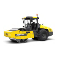
Fig. Fuses
1
2
3
4
5
6
7
8
9
10
11
12
13
14
15
16
The figure shows the position of the fuses.
The table below gives fuse amperage and function. All
fuses are flat pin fuses.
1. Main relay, 24V outlet engine
compartment
10A 9. Reserve1. Main relay, 24V outlet engine
compartment
10A 9. Reserve
2. ECU, Outlet boot loading, I/O board,
display
5A 10. Reserve2. ECU, Outlet boot loading, I/O board,
display
5A 10. Reserve
3. ECU PWR1, Speed sensor 10A 11. 12V outlet, Radio/CD 10A3. ECU PWR1, Speed sensor 10A 11. 12V outlet, Radio/CD 10A
4. ECU PWR2, Forward/Reverse lever 10A 12. GPS, DCM, DCO, tilt sensor 10A4. ECU PWR2, Forward/Reverse lever 10A 12. GPS, DCM, DCO, tilt sensor 10A
5. ECU PWR 3 20A 13. Reserve5. ECU PWR 3 20A 13. Reserve
6. ECU PWR 4 20A 14. DCA 10A6. ECU PWR 4 20A 14. DCA 10A
7. 24V outlet operator's station,
Tachograph
10A 15. Indicator relay 7.5A7. 24V outlet operator's station,
Tachograph
10A 15. Indicator relay 7.5A
8. Hydraulic/Fuel sensor, Engine 10A 16. Driving lights 10A8. Hydraulic/Fuel sensor, Engine 10A 16. Driving lights 10A
Fuses at master switch (Cummins)
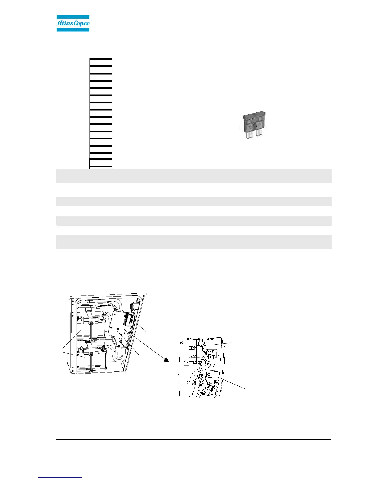
Fig. Cover, left side
1. Fuse box
2. Batteries (x2)
3. Battery disconnector plate
1
3
2
The fuse box (1) is located inside the cover by the
steps on the left-hand side of the roller.
This is also where the batteries (2) are, and the starter
relay (4) and preheating relay (5) are placed behind
the battery disconnector plate (3).
5
4
4. Starter relay, 50A
5. Preheating relay, 120A
53
 Loading...