149
7647H–AVR–03/12
Atmel ATmega16/32/64/M1/C1
Used in Fault mode 7, PSCn Input A or PSCn Input B act indifferently on On-Time0/Dead-Time0
or on On-Time1/Dead-Time1.
14.12 Analog Synchronization
Each PSC module generates a signal to synchronize the ADC sample and hold; synchronisation
is mandatory for measurements.
This signal can be selected between all falling or rising edge of PSCOUTnA or PSCOUTnB
outputs.
In center aligned mode, OCRnRAH/L is not used, so it can be used to specified the synchroniza-
tion of the ADC. It this case, it’s minimum value is 1.
14.13 Interrupt Handling
As each PSC module can be dedicated for one function, each PSC has its own interrupt system
(vector ...)
List of interrupt sources:
• Counter reload (end of On Time 1)
• PSC Input event (active edge or at the beginning of level configured event)
• PSC Mutual Synchronization Error
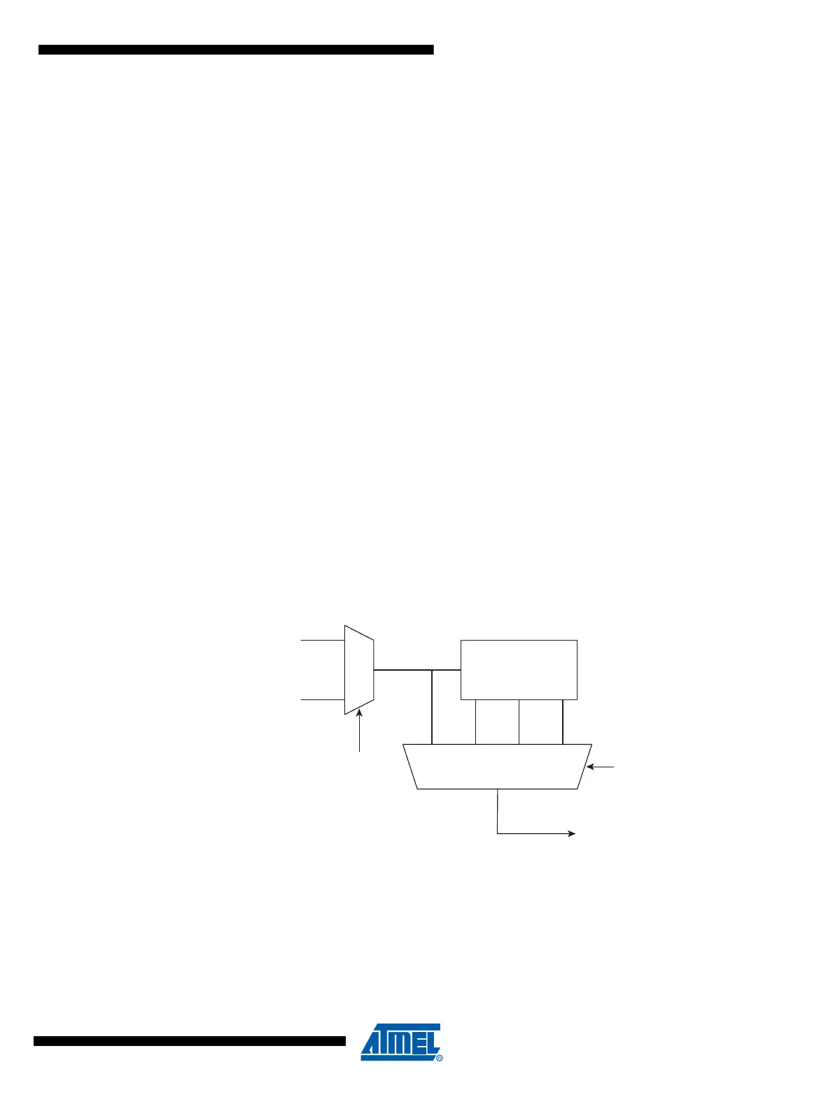
14.14 PSC Clock Sources
Each PSC has two clock inputs:
• CLK PLL from the PLL
•CLK I/O
Figure 14-15. Clock selection
PCLKSELn bit in PSC Control Register (PCTL) is used to select the clock source.
PPREn1/0 bits in PSC Control Register (PCTL) are used to select the divide factor of the clock.
CLK
CLK
PSCn
CLK
PLL
I/O
CK
CK/4
CK/32
CK/256
PRESCALER
CK
PPREn1/0
00
01
10
11
PCLKSEL
1
0