36
7647H–AVR–03/12
Atmel ATmega16/32/64/M1/C1
5.6.2 PLL Control and Status Register – PLLCSR
• Bit 7..3 – Res: Reserved Bits
These bits are reserved bits in the ATmega16/32/64/M1/C1 and always read as zero.
• Bit 2 – PLLF: PLL Factor
The PLLF bit is used to select the division factor of the PLL.
If PLLF is set, the PLL output is 64MHz.
If PLLF is clear, the PLL output is 32MHz.
• Bit 1 – PLLE: PLL Enable
When the PLLE is set, the PLL is started and if not yet started the internal RC Oscillator is
started as PLL reference clock. If PLL is selected as a system clock source the value for this bit
is always 1.
• Bit 0 – PLOCK: PLL Lock Detector
When the PLOCK bit is set, the PLL is locked to the reference clock, and it is safe to enable
CLK
PLL
for Fast Peripherals. After the PLL is enabled, it takes about 100 µs for the PLL to lock.
5.7 128 kHz Internal Oscillator
The 128 kHz internal Oscillator is a low power Oscillator providing a clock of 128 kHz. The fre-
quency is nominal at 3V and 25°C. This clock is used by the Watchdog Oscillator.
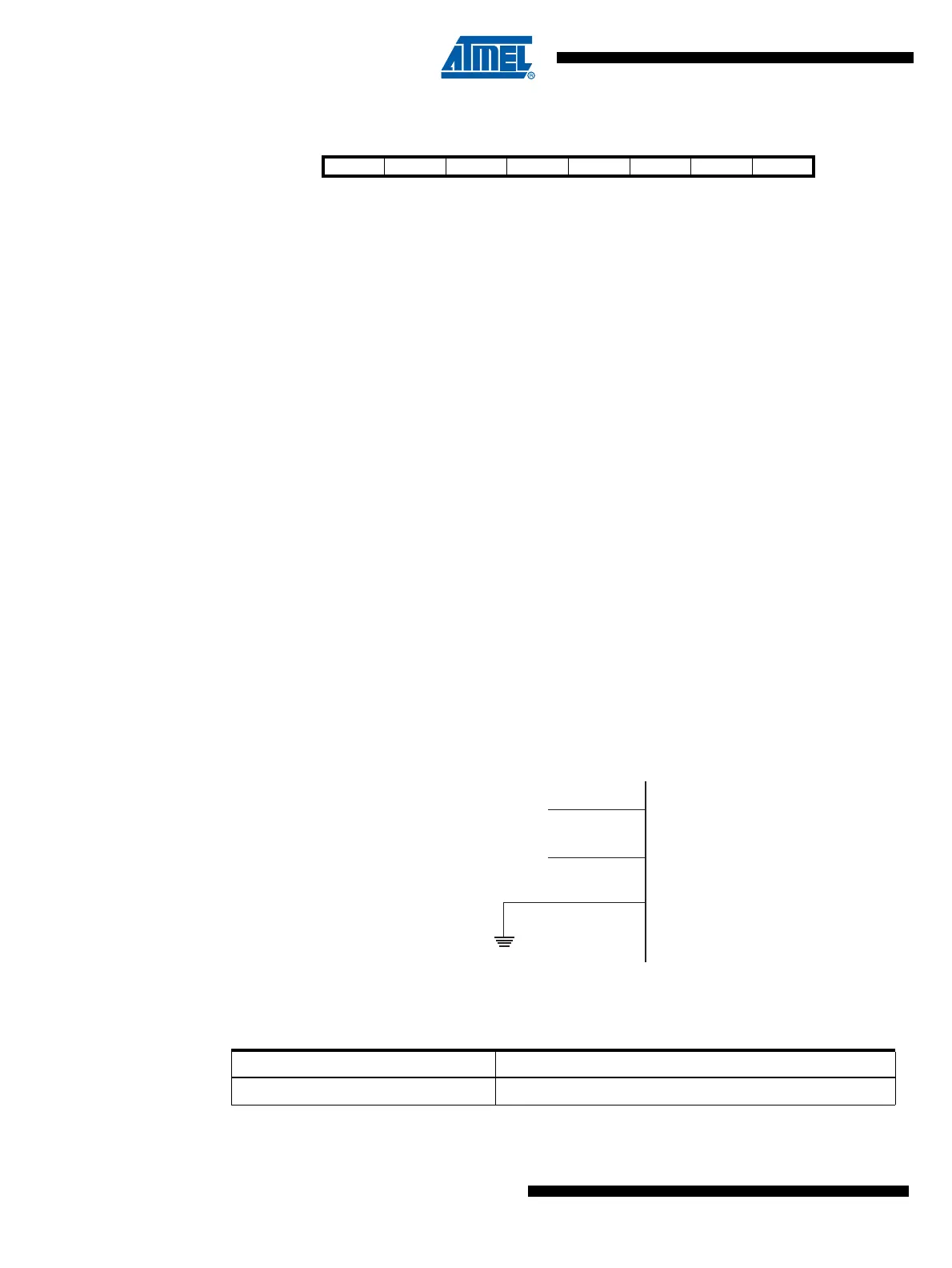
5.8 External Clock
To drive the device from an external clock source, XTAL1 should be driven as shown in Figure
5-4. To run the device on an external clock, the CKSEL Fuses must be programmed to “0000”.
Figure 5-4. External Clock Drive Configuration
Bit 76543210
$29 ($29) –––––PLLFPLLEPLOCKPLLCSR
Read/Write R R R R R R/W R/W R
Initial Value0000000/10
Table 5-8. External Clock Frequency
CKSEL3..0 Frequency Range
0000 0 - 16MHz
XTAL2
XTAL1
GND
NC
External
Clock
Signal