175
7647H–AVR–03/12
Atmel ATmega16/32/64/M1/C1
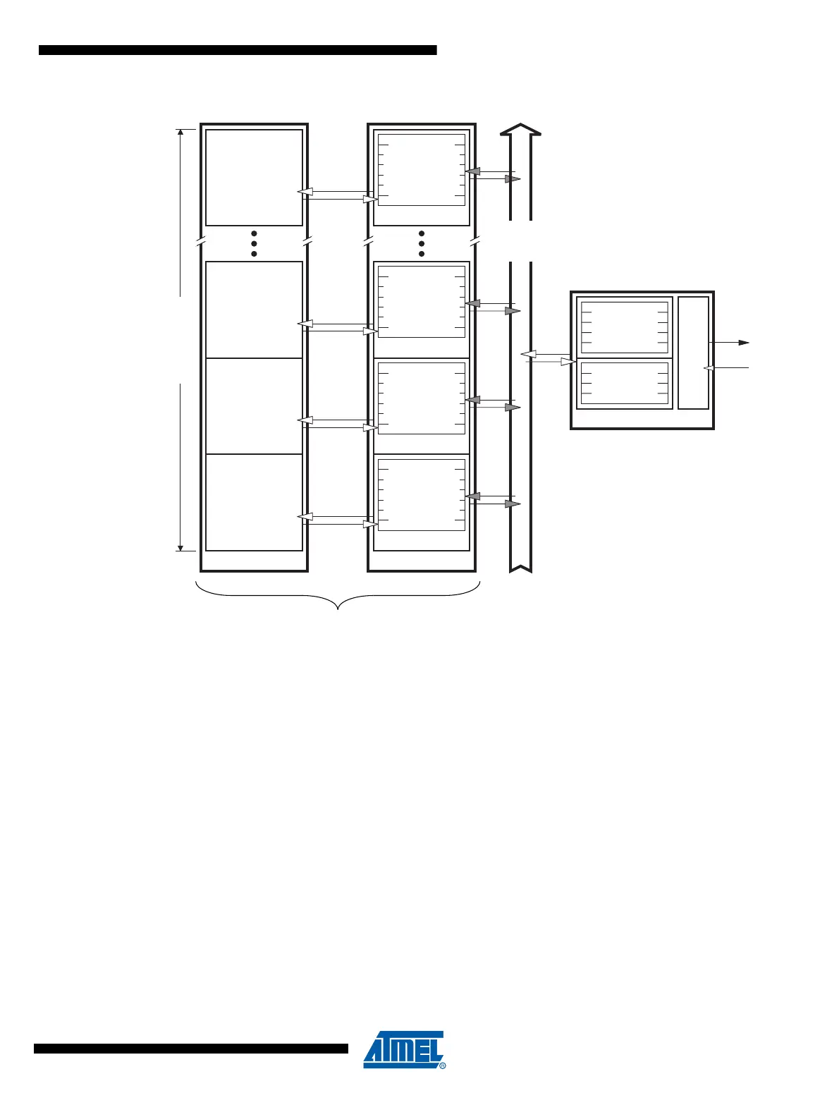
Figure 16-5. CAN Controller Structure
16.4 CAN Channel
16.4.1 Configuration
The CAN channel can be in:
• Enabled mode
In this mode:
– the CAN channel (internal TxCAN & RxCAN) is enabled,
– the input clock is enabled.
• Standby mode
In standby mode:
– the transmitter constantly provides a recessive level (on internal TxCAN) and the
receiver is disabled,
– input clock is enabled,
– the registers and pages remain accessible.
• Listening mode
This mode is transparent for the CAN channel:
CAN Channel
Gen. Control
Gen. Status
Enable MOb
Interrupt
Bit Timing
Line Error
CAN Timer
LCC
MAC
PLS
Internal
TxCAN
Internal
RxCAN
Mailbox
Message Objets
MOb0
MOb1
MOb2
MOb i
Control
Status
IDtag+IDmask
Time Stamp
Control
Status
IDtag+IDmask
Time Stamp
Control
Status
IDtag+IDmask
Time Stamp
Control
Status
IDtag+IDmask
Time Stamp
Buffer MOb0
Buffer MOb1
Buffer MOb2
Buffer MOb i
CAN Data Buffers
Size=120 Bytes
Low priority
High priority
MOb
Scanning