283
7647H–AVR–03/12
Atmel ATmega16/32/64/M1/C1
Note: 1. “1” means unprogrammed, “0” means programmed
Note: “1” means unprogrammed, “0” means programmed
24.5 Entering the Boot Loader Program
Entering the Boot Loader takes place by a jump or call from the application program. This may
be initiated by a trigger such as a command received via UART, or SPI interface. Alternatively,
the Boot Reset Fuse can be programmed so that the Reset Vector is pointing to the Boot Flash
start address after a reset. In this case, the Boot Loader is started after a reset. After the applica-
tion code is loaded, the program can start executing the application code. Note that the fuses
cannot be changed by the MCU itself. This means that once the Boot Reset Fuse is pro-
grammed, the Reset Vector will always point to the Boot Loader Reset and the fuse can only be
changed through the serial or parallel programming interface.
Note: 1. “1” means unprogrammed, “0” means programmed
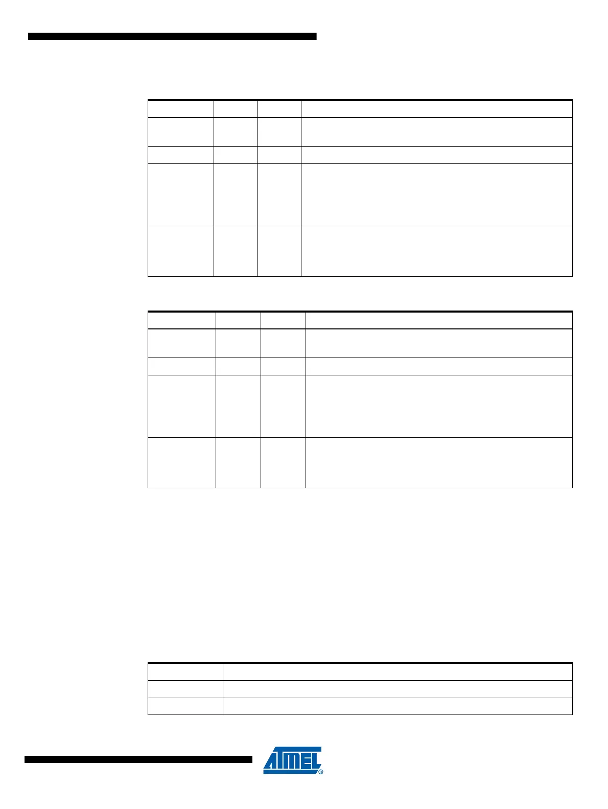
Table 24-2. Boot Lock Bit0 Protection Modes (Application Section)
(1)
BLB0 Mode BLB02 BLB01 Protection
111
No restrictions for SPM or LPM accessing the Application
section.
2 1 0 SPM is not allowed to write to the Application section.
300
SPM is not allowed to write to the Application section, and LPM
executing from the Boot Loader section is not allowed to read
from the Application section. If Interrupt Vectors are placed in
the Boot Loader section, interrupts are disabled while executing
from the Application section.
401
LPM executing from the Boot Loader section is not allowed to
read from the Application section. If Interrupt Vectors are placed
in the Boot Loader section, interrupts are disabled while
executing from the Application section.
Table 24-3. Boot Lock Bit1 Protection Modes (Boot Loader Section)
(Note:)
BLB1 Mode BLB12 BLB11 Protection
111
No restrictions for SPM or LPM accessing the Boot Loader
section.
2 1 0 SPM is not allowed to write to the Boot Loader section.
300
SPM is not allowed to write to the Boot Loader section, and
LPM executing from the Application section is not allowed to
read from the Boot Loader section. If Interrupt Vectors are
placed in the Application section, interrupts are disabled while
executing from the Boot Loader section.
401
LPM executing from the Application section is not allowed to
read from the Boot Loader section. If Interrupt Vectors are
placed in the Application section, interrupts are disabled while
executing from the Boot Loader section.
Table 24-4. Boot Reset Fuse
(1)
BOOTRST Reset Address
1 Reset Vector = Application Reset (address 0x0000)
0 Reset Vector = Boot Loader Reset (see Table 24-7 on page 292)