254
7647H–AVR–03/12
Atmel ATmega16/32/64/M1/C1
18.11 Amplifier Control Registers
The configuration of the amplifiers are controlled via two dedicated registers AMP0CSR and
AMP1CSR. Then the start of conversion is done via the ADC control and status registers.
The conversion result is stored on ADCH and ADCL register which contain respectively the most
significant bits and the less significant bits.
18.11.1 Amplifier 0 Control and Status register – AMP0CSR
• Bit 7 – AMP0EN: Amplifier 0 Enable Bit
Set this bit to enable the Amplifier 0.
Clear this bit to disable the Amplifier 0.
Clearing this bit while a conversion is running will take effect at the end of the conversion.
Warning: Always clear AMP0TS0:1 when clearing AMP0EN.
• Bit 6 – AMP0IS: Amplifier 0 Input Shunt
Set this bit to short-circuit the Amplifier 0 input.
Clear this bit to normally use the Amplifier 0.
• Bit 5, 4 – AMP0G1, 0: Amplifier 0 Gain Selection Bits
These 2 bits determine the gain of the amplifier 0.
The different setting are shown in Table 18-8.
To ensure an accurate result, after the gain value has been changed, the amplifier input needs
to have a quite stable input value during at least 4 Amplifier synchronization clock periods.
• Bit 3 – AMPCMP0: Amplifier 0 - Comparator 0 connection
Set this bit to connect the amplifier 0 to the comparator 0 positive input. In this configuration the
comparator clock is twice the amplifier clock.
Clear this bit to normally use the Amplifier 0.
• Bit 2:0 – AMP0TS2,AMP0TS1,AMP0TS0: Amplifier 0 Clock Source Selection Bits
In accordance with the Table 18-9, these 3 bits select the event which will generate the clock for
the amplifier 0. This clock source is necessary to start the conversion on the amplified channel.
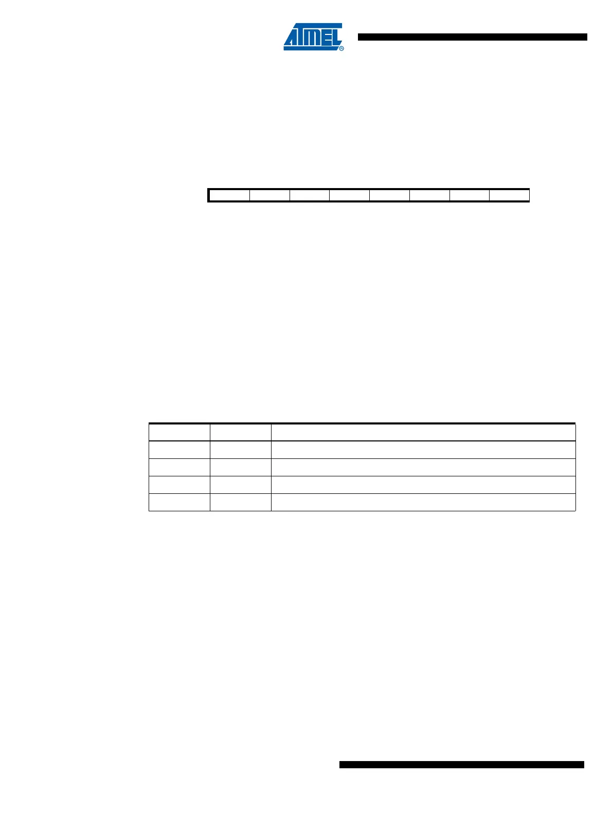
Bit 76543210
AMP0EN AMP0IS AMP0G1 AMP0G0 AMPCMP0 AMP0TS2 AMP0TS1 AMP0TS0 AMP0CSR
Read/Write R/W R/W R/W R/W R/W R/W R/W R/W
Initial Value 00000000
Table 18-8. Amplifier 0 Gain Selection
AMP0G1 AMP0G0 Description
00Gain 5
01Gain 10
10Gain 20
11Gain 40