296
7647H–AVR–03/12
Atmel ATmega16/32/64/M1/C1
25. Memory Programming
25.1 Program And Data Memory Lock Bits
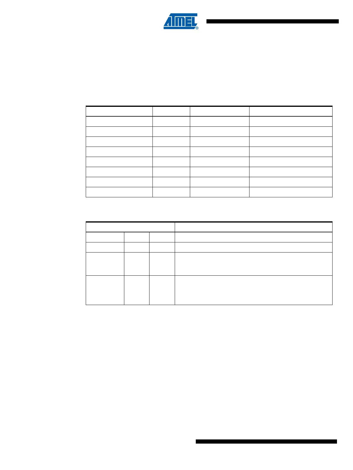
The ATmega16/32/64/M1/C1 provides six Lock bits which can be left unprogrammed (“1”) or can
be programmed (“0”) to obtain the additional features listed in Table 25-2. The Lock bits can only
be erased to “1” with the Chip Erase command.
Notes: 1. “1” means unprogrammed, “0” means programmed.
Notes: 1. Program the Fuse bits and Boot Lock bits before programming the LB1 and LB2.
2. “1” means unprogrammed, “0” means programmed
Table 25-1. Lock Bit Byte
(1)
Lock Bit Byte Bit No Description Default Value
7 – 1 (unprogrammed)
6 – 1 (unprogrammed)
BLB12 5 Boot Lock bit 1 (unprogrammed)
BLB11 4 Boot Lock bit 1 (unprogrammed)
BLB02 3 Boot Lock bit 1 (unprogrammed)
BLB01 2 Boot Lock bit 1 (unprogrammed)
LB2 1 Lock bit 1 (unprogrammed)
LB1 0 Lock bit 1 (unprogrammed)
Table 25-2. Lock Bit Protection Modes
(1)(2)
Memory Lock Bits Protection Type
LB Mode LB2 LB1
1 1 1 No memory lock features enabled.
210
Further programming of the Flash and EEPROM is disabled in
Parallel and Serial Programming mode. The Fuse bits are
locked in both Serial and Parallel Programming mode.
(1)
300
Further programming and verification of the Flash and
EEPROM is disabled in Parallel and Serial Programming mode.
The Boot Lock bits and Fuse bits are locked in both Serial and
Parallel Programming mode.
(1)