212
7647H–AVR–03/12
Atmel ATmega16/32/64/M1/C1
17.5 LIN / UART Description
17.5.1 Reset
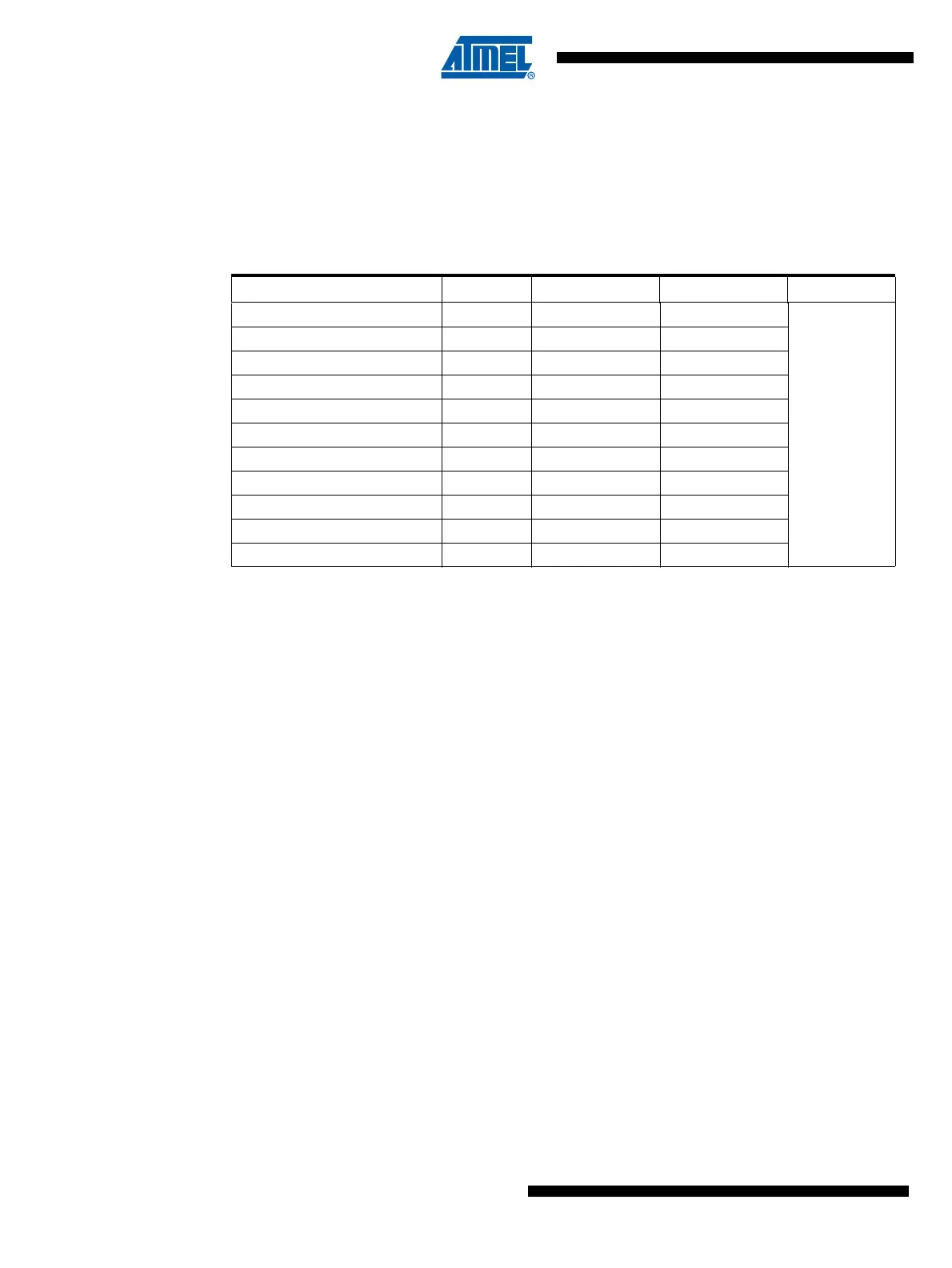
The AVR core reset logic signal also resets the LIN/UART controller. Another form of reset
exists, a software reset controlled by LSWRES bit in LINCR register. This self-reset bit performs
a partial reset as shown in Table 17-2.
17.5.2 Clock
The I/O clock signal (clk
i/o
) also clocks the LIN/UART controller. It is its unique clock.
17.5.3 LIN Protocol Selection
LIN13 bit in LINCR register is used to select the LIN protocol:
• LIN13 = 0 (default): LIN 2.1 protocol,
• LIN13 = 1: LIN 1.3 protocol.
The controller checks the LIN13 bit in computing the checksum (enhanced checksum in LIN2.1 /
classic checksum in LIN 1.3). See “Rx & TX Response Functions” on page 210.
This bit is irrelevant for UART commands.
Table 17-2. Reset of LIN/UART Registers
Register Name Reset Value LSWRES Value Comment
LIN Control Reg. LINCR
0000 0000
b
0000 0000
b
x=unknown
u=unchanged
LIN Status & Interrupt Reg. LINSIR
0000 0000
b
0000 0000
b
LIN Enable Interrupt Reg. LINENIR
0000 0000
b
xxxx 0000
b
LIN Error Reg. LINERR
0000 0000
b
0000 0000
b
LIN Bit Timing Reg. LINBTR
0010 0000
b
0010 0000
b
LIN Baud Rate Reg. Low LINBRRL
0000 0000
b
uuuu uuuu
b
LIN Baud Rate Reg. High LINBRRH
0000 0000
b
xxxx uuuu
b
LIN Data Length Reg. LINDLR
0000 0000
b
0000 0000
b
LIN Identifier Reg. LINIDR
1000 0000
b
1000 0000
b
LIN Data Buffer Selection LINSEL
0000 0000
b
xxxx 0000
b
LIN Data LINDAT
0000 0000
b
0000 0000
b