213
7647H–AVR–03/12
Atmel ATmega16/32/64/M1/C1
17.5.4 Configuration
Depending on the mode (LIN or UART), LCONF[1..0] bits of the LINCR register set the controller
in the following configuration (Table 17-3):
The LIN configuration is independent of the programmed LIN protocol.
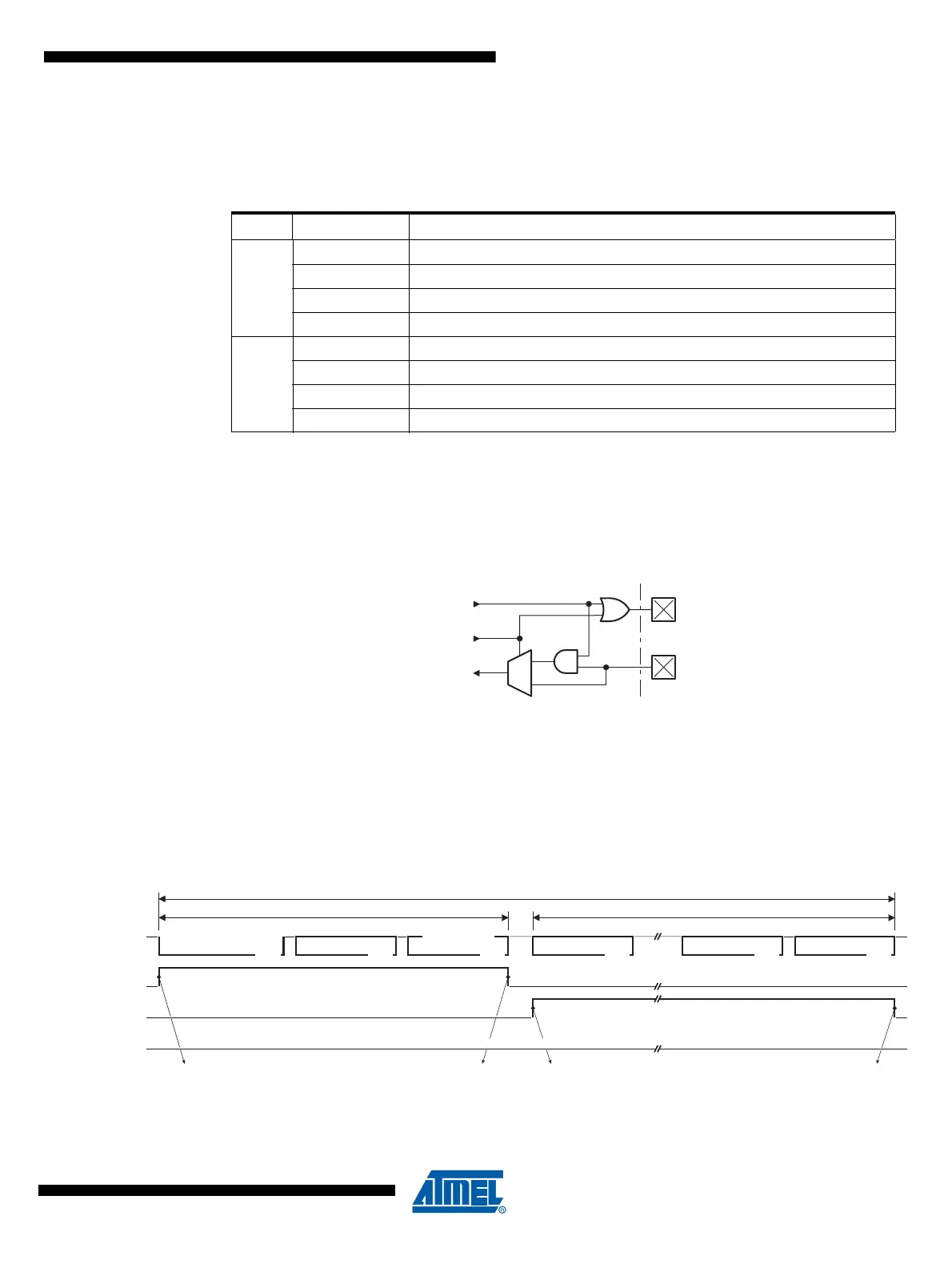
The listening mode connects the internal Tx LIN and the internal Rx LIN together. In this mode,
the TXLIN output pin is disabled and the RXLIN input pin is always enabled. The same scheme
is available in UART mode.
Figure 17-6. Listening Mode
17.5.5 Busy Signal
LBUSY bit flag in LINSIR register is the image of the BUSY signal. It is set and cleared by hard-
ware. It signals that the controller is busy with LIN or UART communication.
17.5.5.1 Busy Signal in LIN Mode
Figure 17-7. Busy Signal in LIN Mode
Table 17-3. Configuration Table versus Mode
Mode LCONF[1..0] Configuration
LIN
00
b
LIN standard configuration (default)
01
b
No CRC field detection or transmission
10
b
Frame_Time_Out disable
11
b
Listening mode
UART
00
b
8-bit data, no parity & 1 stop-bit
01
b
8-bit data, even parity & 1 stop-bit
10
b
8-bit data, odd parity & 1 stop-bit
11
b
Listening mode, 8-bit data, no parity & 1 stop-bit
1
0
TXLIN
RXLIN
internal
Tx LIN
internal
Rx LIN
LISTEN
BREAK
Field
SYNC
Field
CHECKSUM
Field
DATA-0
FieldField
IDENTIFIER
PROTECTED
DATA-n
Field
RESPONSEHEADER
FRAME SLOT
LIN bus
LIDOK
Node providing the master task
Node providing a slave task
LCMD=Tx Header LTXOK or LRXOKLCMD=Tx or Rx Response
1) LBUSY
3) LBUSY
2) LBUSY
Node providing neither the master task, neither a slave task