298
7647H–AVR–03/12
Atmel ATmega16/32/64/M1/C1
Note: 1. See Table 7-2 on page 49 for BODLEVEL Fuse decoding.
25.3 PSC Output Behavior During Reset
For external component safety reason, the state of PSC outputs during Reset can be pro-
grammed by fuses PSCRB, PSCARV & PSCBRV.
These fuses are located in the Extended Fuse Byte ( see Table 25-4)
If PSCRB fuse equals 1 (unprogrammed), all PSC outputs keep a standard port behaviour. If
PSC0RB fuse equals 0 (programmed), all PSC outputs are forced at reset to low level or high
level according to PSCARV and PSCBRV fuse bits. In this second case, the PSC outputs keep
the forced state until POC register is written. See “Clock Prescaler Register – CLKPR” on page
38.
PSCARV (PSCOUTnA Reset Value) gives the state low or high which will be forced on
PSCOUT0A, PSCOUT1A and PSCOUT2A outputs when PSCRB is programmed. If PSCARV
fuse equals 0 (programmed), the PSCOUT0A, PSCOUT1A and PSCOUT2A outputs will be
forced to high state. If PSCRV fuse equals 1 (unprogrammed), the PSCOUT0A, PSCOUT1A
and PSCOUT2A outputs will be forced to low state.
PSCBRV (PSCOUTnB Reset Value) gives the state low or high which will be forced on
PSCOUT0B, PSCOUT1B and PSCOUT2B outputs when PSCRB is programmed. If PSCBRV
fuse equals 0 (programmed), the PSCOUT0B, PSCOUT1B and PSCOUT2B outputs will be
forced to high state. If PSCRV fuse equals 1 (unprogrammed), the PSCOUT0B, PSCOUT1B
and PSCOUT2B outputs will be forced to low state.
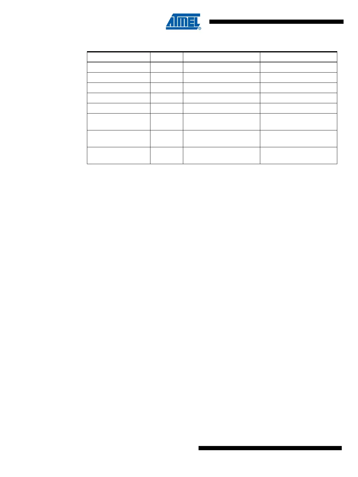
Table 25-4. Extended Fuse Byte
Extended Fuse Byte Bit No Description Default Value
- 7 - 1 (unprogrammed)
- 6 - 1 (unprogrammed)
PSCRB 5 PSC Reset Behaviour 1 (unprogrammed)
PSCRVA 4 PSCOUTnA Reset Value 1 (unprogrammed)
PSCRVB 3 PSCOUTnB Reset Value 1 (unprogrammed)
BODLEVEL2
(1)
2
Brown-out Detector trigger
level
1 (unprogrammed)
BODLEVEL1
(1)
1
Brown-out Detector trigger
level
1 (unprogrammed)
BODLEVEL0
(1)
0
Brown-out Detector trigger
level
1 (unprogrammed)

 Loading...


