49
7647H–AVR–03/12
Atmel ATmega16/32/64/M1/C1
7.2.3 Brown-out Detection
ATmega16/32/64/M1/C1 has an On-chip Brown-out Detection (BOD) circuit for monitoring the
V
CC
level during operation by comparing it to a fixed trigger level. The trigger level for the BOD
can be selected by the BODLEVEL Fuses. The trigger level has a hysteresis to ensure spike
free Brown-out Detection. The hysteresis on the detection level should be interpreted as V
BOT+
=
V
BOT
+ V
HYST
/2 and V
BOT-
= V
BOT
- V
HYST
/2.
Notes: 1. V
BOT
may be below nominal minimum operating voltage for some devices. For devices where
this is the case, the device is tested down to V
CC
= V
BOT
during the production test. This guar-
antees that a Brown-Out Reset will occur before V
CC
drops to a voltage where correct
operation of the microcontroller is no longer guaranteed. The test is performed using
BODLEVEL = 010 for Low Operating Voltage and BODLEVEL = 101 for High Operating Volt-
age .
2. Values are guidelines only.
Notes: 1. Values are guidelines only.
When the BOD is enabled, and V
CC
decreases to a value below the trigger level (V
BOT-
in Figure
7-5 on page 50), the Brown-out Reset is immediately activated. When V
CC
increases above the
trigger level (V
BOT+
in Figure 7-5 on page 50), the delay counter starts the MCU after the
Time-out period t
TOUT
has expired.
The BOD circuit will only detect a drop in V
CC
if the voltage stays below the trigger level for lon-
ger than t
BOD
given in Table 7-3.
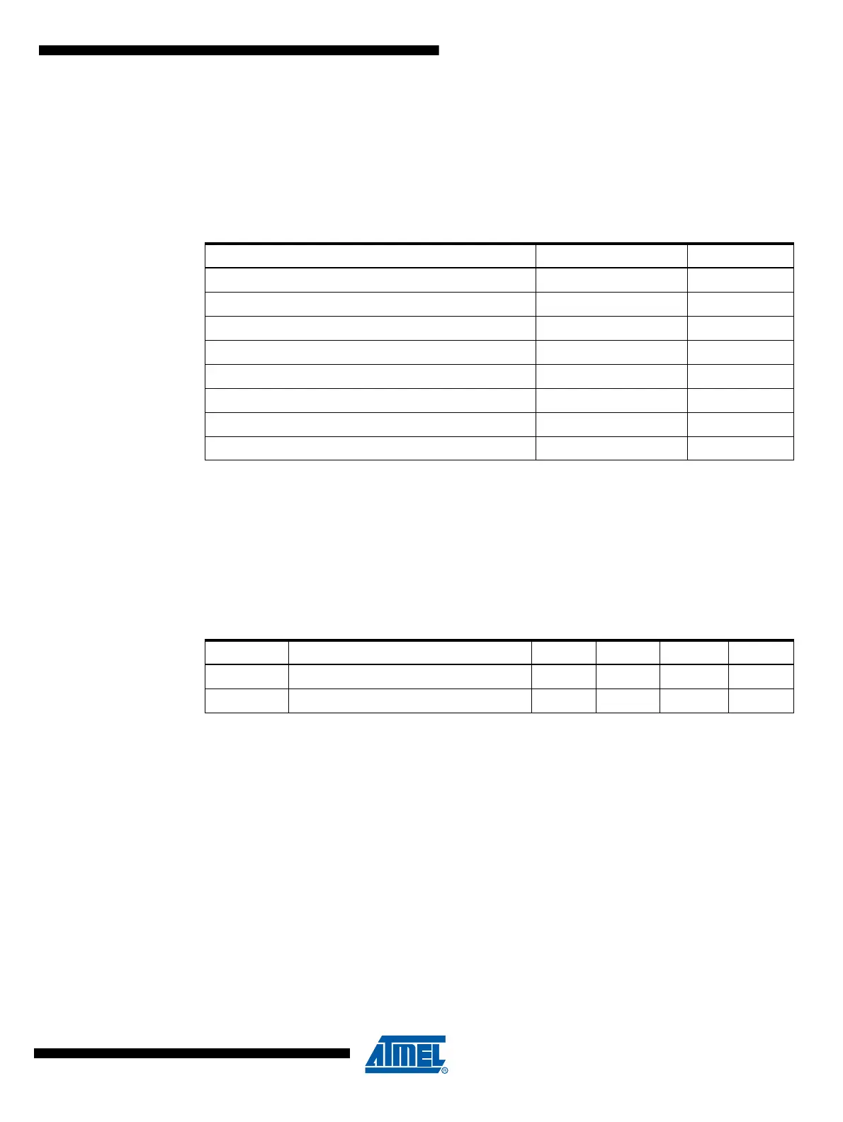
Table 7-2. BODLEVEL Fuse Coding
(1)(2)
BODLEVEL 2..0 Fuses Typ V
BOT
Units
111 Disabled
110 4.5 V
011 4.4 V
100 4.3 V
010 4.2 V
001 2.8 V
101 2.7 V
000 2.6 V
Table 7-3. Brown-out Characteristics
(1)
Symbol Parameter Min. Typ. Max. Units
V
HYST
Brown-out Detector Hysteresis 80 mV
t
BOD
Min Pulse Width on Brown-out Reset 2 µs