31
7647H–AVR–03/12
Atmel ATmega16/32/64/M1/C1
5.3 Default Clock Source
The device is shipped with CKSEL = “0010”, SUT = “10”, and CKDIV8 programmed. The default
clock source setting is the Internal RC Oscillator with longest start-up time and an initial system
clock prescaling of 8. This default setting ensures that all users can make their desired clock
source setting using an In-System or Parallel programmer.
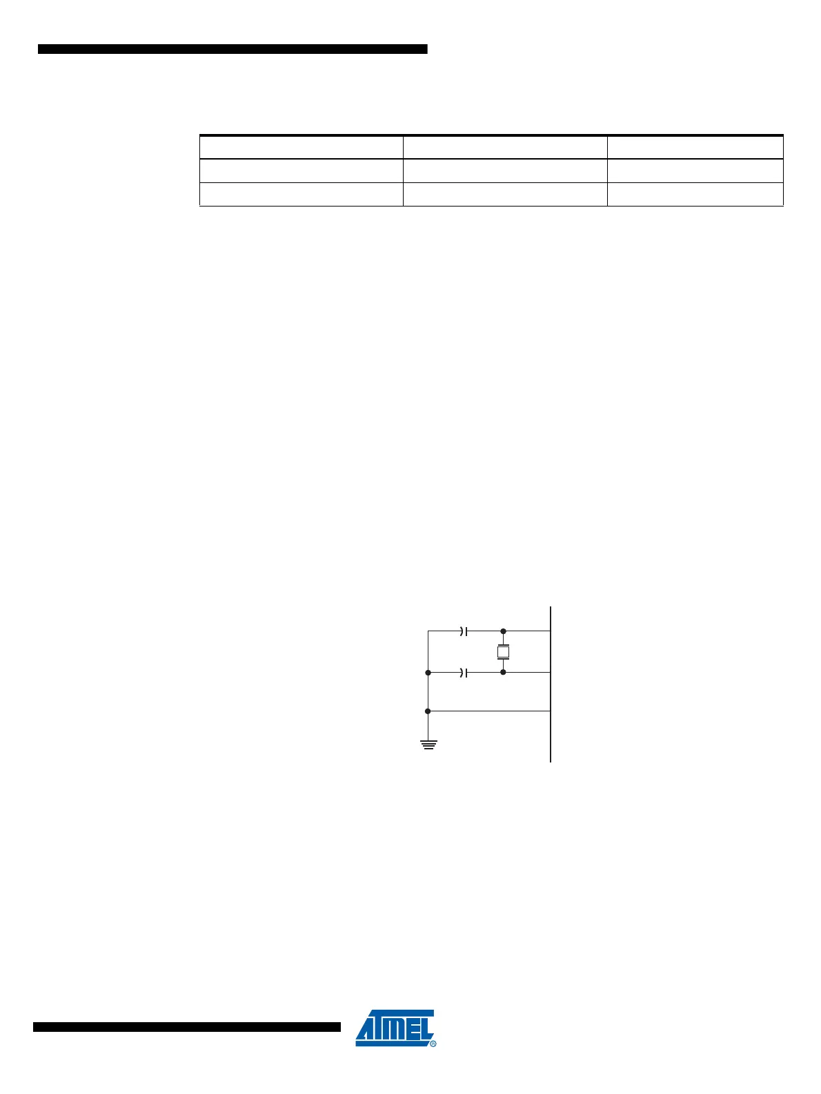
5.4 Low Power Crystal Oscillator
XTAL1 and XTAL2 are input and output, respectively, of an inverting amplifier which can be con-
figured for use as an On-chip Oscillator, as shown in Figure 5-2. Either a quartz crystal or a
ceramic resonator may be used.
This Crystal Oscillator is a low power oscillator, with reduced voltage swing on the XTAL2 out-
put. It gives the lowest power consumption, but is not capable of driving other clock inputs.
C1 and C2 should always be equal for both crystals and resonators. The optimal value of the
capacitors depends on the crystal or resonator in use, the amount of stray capacitance, and the
electromagnetic noise of the environment. Some initial guidelines for choosing capacitors for
use with crystals are given in Table 5-3. For ceramic resonators, the capacitor values given by
the manufacturer should be used. For more information on how to choose capacitors and other
details on Oscillator operation, refer to the Multi-purpose Oscillator Application Note.
Figure 5-2. Crystal Oscillator Connections
Table 5-2. Number of Watchdog Oscillator Cycles
Typ Time-out (V
CC
= 5.0V) Typ Time-out (V
CC
= 3.0V) Number of Cycles
4.1 ms 4.3 ms 4K (4,096)
65 ms 69 ms 64K (65,536)