32
7647H–AVR–03/12
Atmel ATmega16/32/64/M1/C1
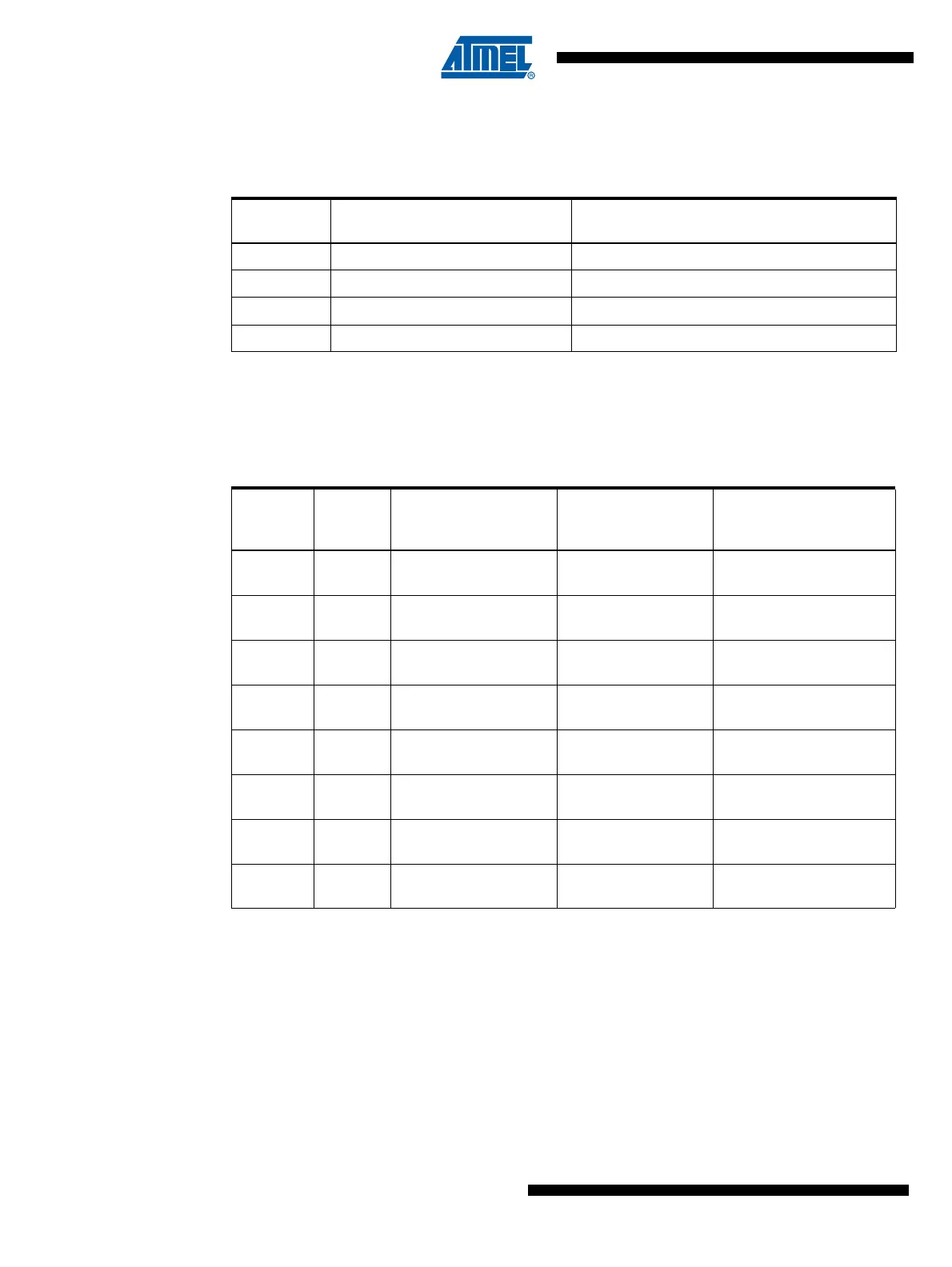
The Oscillator can operate in three different modes, each optimized for a specific frequency
range. The operating mode is selected by the fuses CKSEL3..1 as shown in Table 5-3.
Notes: 1. This option should not be used with crystals, only with ceramic resonators.
The CKSEL0 Fuse together with the SUT1..0 Fuses select the start-up times as shown in Table
5-4.
Notes: 1. These options should only be used when not operating close to the maximum frequency of the
device, and only if frequency stability at start-up is not important for the application. These
options are not suitable for crystals.
2. These options are intended for use with ceramic resonators and will ensure frequency stability
at start-up. They can also be used with crystals when not operating close to the maximum fre-
quency of the device, and if frequency stability at start-up is not important for the application.
Table 5-3. Crystal Oscillator Operating Modes
CKSEL3..1 Frequency Range (MHz)
Recommended Range for Capacitors C1 and
C2 for Use with Crystals (pF)
100
(1)
0.4 - 0.9 –
101 0.9 - 3.0 12 - 22
110 3.0 - 8.0 12 - 22
111 8.0 -16.0 12 - 22
Table 5-4. Start-up Times for the Oscillator Clock Selection
CKSEL0 SUT1..0
Start-up Time from
Power-down and
Power-save
Additional Delay
from Reset
(V
CC
= 5.0V) Recommended Usage
000 258 CK
(1)
14CK + 4.1 ms
Ceramic resonator, fast
rising power
001 258 CK
(1)
14CK + 65 ms
Ceramic resonator,
slowly rising power
010 1K CK
(2)
14CK
Ceramic resonator, BOD
enabled
011 1K CK
(2)
14CK + 4.1 ms
Ceramic resonator, fast
rising power
100 1K CK
(2)
14CK + 65 ms
Ceramic resonator,
slowly rising power
1 01 16K CK 14CK
Crystal Oscillator, BOD
enabled
1 10 16K CK 14CK + 4.1 ms
Crystal Oscillator, fast
rising power
1 11 16K CK 14CK + 65 ms
Crystal Oscillator, slowly
rising power