217
7647H–AVR–03/12
Atmel ATmega16/32/64/M1/C1
17.5.7.4 Data Length in Tx Response
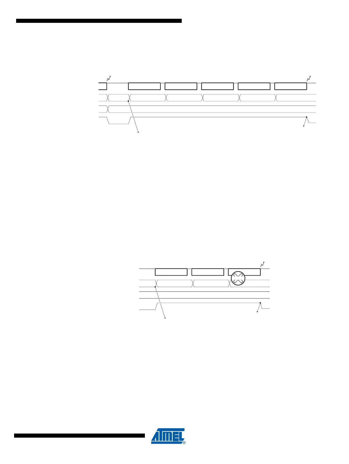
Figure 17-10. LIN1.3 - Tx Response - No error
• The user initializes LTXDL field before setting the Tx Response command,
• After setting the Tx Response command, LRXDL is reset by hardware,
• LTXDL will remain unchanged during Tx (during busy signal),
• LRXDL will count the number of transmitted bytes (during busy signal),
• If an error occurs, Tx stops, the corresponding error flag is set and LRXDL will give the
number of transmitted bytes without error,
• If no error occurs, LTXOK is set after the transmission of the CHECKSUM, LTXDL will be
unchanged (and LRXDL = LTXDL).
17.5.7.5 Data Length after Error
Figure 17-11. Tx Response - Error
Note: Information on response (ex: error on byte) is only available at the end of the serialization/de-seri-
alization of the byte.
17.5.7.6 Data Length in UART Mode
• The UART mode forces LRXDL and LTXDL to 0 and disables the writing in LINDLR register,
• Note that after reset, LRXDL and LTXDL are also forced to 0.
DATA-0 DATA-1 DATA-2 DATA-3 CHECKSUM
LCMD2..0=000
b
LIN bus
LBUSY
1
st
Byte 2
nd
Byte 3
rd
Byte 4
th
Byte
LIDOK LTXOK
140
LRXDL (*)
234
LCMD=Tx Response
(*) : LRXDL & LTXDL updated by Rx Response or Tx Response task
LTXDL (*)
4
DATA-0 DATA-1
LCMD2..0=000
b
LIN bus
LBUSY
1
st
Byte 2
nd
Byte 3
rd
Byte
LERR
140
LRXDL
2
LCMD=Tx Response
LTXDL
4
DATA-2
ERROR

 Loading...