7
2.2.1 Function Description
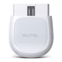
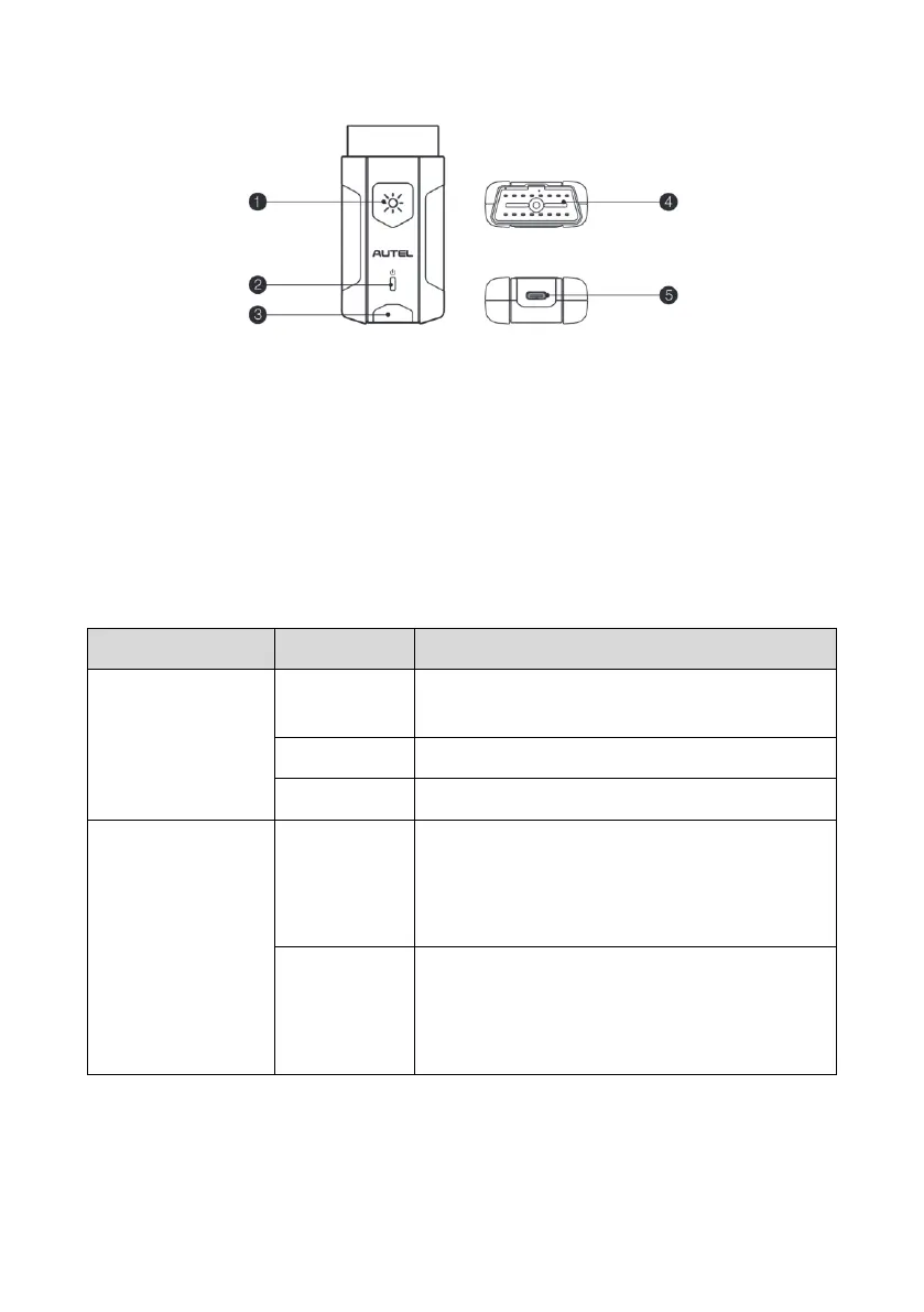
Figure 2-4 MaxiVCI V200 Views
1. Flashlight Power Button
2. Power LED — refer to Table 2-2 VCI LED Description for details
3. Vehicle/Connection LED — refer to Table 2-2 VCI LED Description for details
4. Vehicle Data Connector (16-pin)
5. USB Port
Table 2-2 VCI LED Description
The VCI is powered on and performing self-
check.
The VCI is ready for use.
The firmware is updating.
⚫ Solid Green: The VCI is connected via
USB cable.
⚫ Flashing Green: The VCI is
communicating via USB cable.
⚫ Solid Blue: The VCI is connected via
Bluetooth.
⚫ Flashing Blue: The VCI is communicating
via Bluetooth.