16
4 TPMS
The MaxiTPMS tablet provides an extensive series of TPMS-related services and
functions. Quickly identifying vehicle information and easy to operate, the tablet is an
ideal choice for technicians to complete TPMS work.
4.1 Establishing Vehicle Communication
Prior to performing the TPMS function, ensure the MaxiTPMS tablet is connected to the
test vehicle through the MaxiVCI V200. To establish a proper vehicle communication
between the tablet and the test vehicle, you can perform the following steps:
1. Connect the MaxiVCI V200 to the vehicle’s DLC for both communication and power
supply.
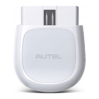
2. Connect the MaxiVCI V200 to the MaxiTPMS tablet via Bluetooth connection or
using a USB-C to USB-C cable (not included).
3. A green “ √ ” mark will be displayed on the VCI status icon, indicating the
communication between the MaxiVCI V200 and the MaxiTPMS tablet has been
established, and the tablet is ready for vehicle diagnosis.
4.1.1 Vehicle Connection
To connect the MaxiVCI V200 device to the test vehicle, insert the vehicle data connector
on the MaxiVCI V200 into the vehicle’s DLC which is usually located under the vehicle
dashboard, and the MaxiVCI V200 will be automatically powered on.
NOTE
The vehicle’s DLC is not always located under the dashboard. Refer to the vehicle’s user
manual for DLC location.
4.1.2 VCI Connection
After the MaxiVCI V200 device is properly connected to the vehicle, the Power LED
illuminates solid green, indicating that it is ready to establish a communication with the
MaxiTPMS tablet.
The MaxiVCI V200 device supports two communication methods with the MaxiTPMS
tablet: Bluetooth or USB-C to USB-C cable connection.