Page 24 of 78
3.7 AC-MXNET-SW24
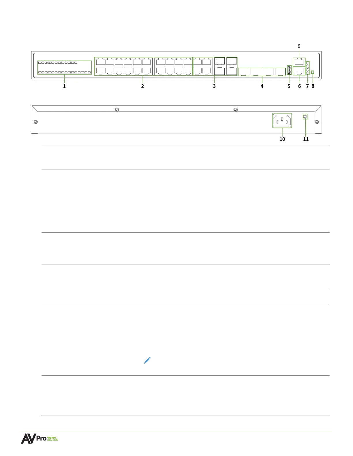
24-Port Network Switch Front Panel
24-Port Network Switch Rear Panel
Green LED status indicator lights
• Steady flickering green lights to indicate network activity is present
-20
(8x) 8-pin RJ-45 female connector ports, 1000BASE-T copper Ethernet
• Supports standard PoE power, IEEE 802.3AF (15.4 W)
• Maximum power consumption of 6.5 W
• 10/100/1000Mbps auto-negotiation
• MDI/MDI-X cable mode auto-negotiation
• Maximum distance 100m (330ft) over Cat5e and higher
• Connects to the encoders, decoders, and CBOX
25-28
Supports a 1 Gigabit Ethernet copper connection or SFP fiber module
for longer runs to the BI DIR. O.M. LC Fiber port on the encoders and
10 GIGABIT/SFP+
PORTS 49-52
Used for stacking multiple network switches together with 40G link
aggregation
• Used for managing the switch’s network configuration settings
8-pin RJ-45 female connector port
• Used for managing the switch’s network configuration settings and
tracking system data.
• Connects to any port (2-7) on the AC-MXNET-CBOX for tracking switch
performance using the Mentor web UI.
NOTE: This is a required physical connection in order to fully access the
switch’s Switch Management page within the Mentor web UI.
POE LED remains solid green to indicate PoE is present on the switch
• DIAG LED steadily flashes green to indicate a continuous diagnostic of
the system is running on normal operations
• PWR LED remains solid green to indicate the switch is powered on