1640-IN-031-C-08 Page 39 of 104
MACO Series Controller Installation
Eurotherm/Barber-Colman
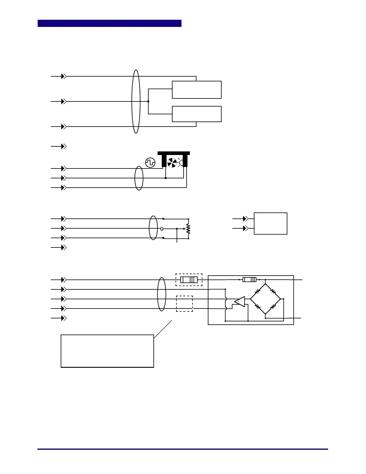
Figure 5.2 Analog I/O Wiring (Connector P3)
1
2
3
4
5
6
7
8
9
10
11
12
13
14
15
16 Analog Output #3
Analog Common
Analog Output #4
No Connection
Tach Input
12 Vdc Common
12 Vdc Regulated
Common
0-10 Vdc
Input (+)
or
2K to 10K
Pot.
Mechanical
link to EJECTOR
EX(-)
EX(+)
SIG(-)
SIG(+)
Shunt Cal Hydraulic 2A/Cal Ana In_4A
Shunt Cal Hydraulic 2B/Cal Ana In_4B
Clamp Hydraulic Input/Ana In_4
Analog Common
ANALOG I/O CARD
CONNECTOR ASSEMBLY
P
Analog Outputs can be either 0 to -10 Vdc or 0 to +10 Vdc
(by Hydraulics Control Relay - see Programming and Setup)
Output current limited to approx. 3mA.
High Level Transducer
Note that ALL Analog Common Terminals are common to each other.
Analog Common
Ejector Position Input/Ana In_3
Ejector Excitation (+)/Ana In_3 EX+
12 Vdc regulated supply load must be limited to
maximum current of 10 mA.
If external supply is used, tie supply minus (-)
to 12 Vdc Common.
High Level Excitation is from external regulated supply.
If transducer does not have built-in Cal resistor, insert resistor
shown between EX (-) and Terminal 5.
If resistor is NOT built-in, use value specified by manufacturer.
8
9
Valve Driver/
Servo Amplifier
Valve Driver/
Servo Amplifier
Analog Inputs must have minimum
Span of 8 Vdc to maintain max. resolution.
See Programming and Setup for 5 Vdc Spans.
Refer to I/O Specs
for detailed description
of I/O devices.
(external) or (built-in)
opto-isolator
Note that certain transducers
may require the installation of an
optical isolator between the transducer
output and analog input terminals.
No Connection
No Connection
 Loading...
