1640-IN-031-C-08 Page 71 of 104
MACO Series Controller Installation
Eurotherm/Barber-Colman
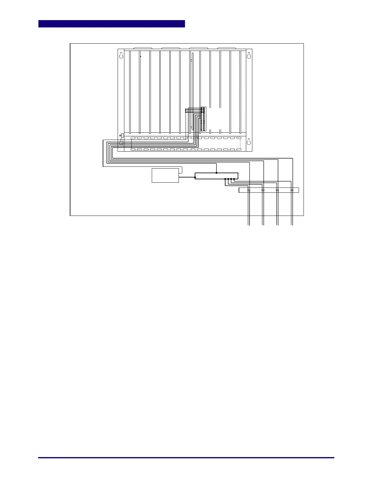
Figure 10.3 Wiring the DC Output Board
DC-
DC+
DC Out 1
DC Out 2
DC Out ...
DC Common
24 Vdc
Supply
+
-
Power Supply outputs MUST have
ferrite beads capable of filtering
30 MHZ to 100 MHZ
Note that NO Shield or Overbraid is necessary.
 Loading...
