1640-IN-031-C-08
Page 22 of 104
Eurotherm/Barber-Colman
MACO Series Controller Installation
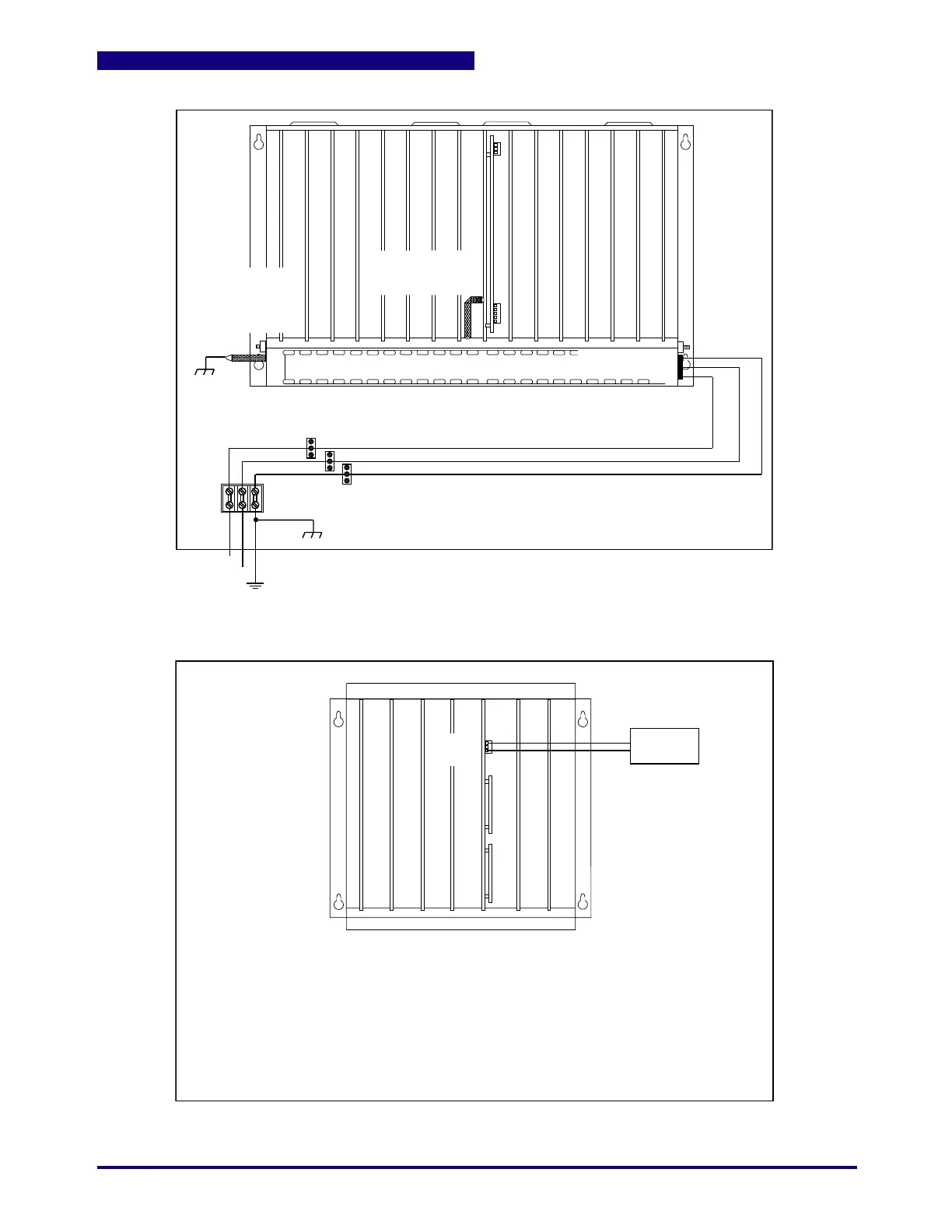
Figure 1.14 AC Power Connections for 16 Slot Controllers
L1
L2 Local
Ground Rod
Include a switch or circuit breaker in the installation. It must be placed in
close proximity to the equipment, within easy reach of the operator and
must be marked as the disconnecting device for the equipment.
Distribution Blocks
Bond to
Chassis
Twist L1, L2 and Safety Earth at least 1 turn per inch.
Safety Earth
Earth (Safety Earth)
L2
L1
Bond to Chassis
within 10 cm of controller
Use the bond strap provided
or one that maintains a 5:1
length to width ratio
Power supply bond strap
is installed at the factory
for CE EMC compliant
systems.
Include a switch or circuit breaker in the installation. It must be placed in
close proximity to the equipment, within easy reach of the operator and
must be marked as the disconnecting device for the equipment.
+24V
N/C
COM
24 Vdc
Supply
+
-
Power Supply outputs MUST have
ferrite beads capable of filtering
30 MHZ to 100 MHZ
A Class 2 Supply is required
24 Vdc, 2.0 Amps (minimum)
24 Vdc, 3.0 Amps (recommended)
DC Power ONLY!
Figure 1.15 DC Power Connection for 7 Slot Controllers
 Loading...
