1640-IN-031-C-08 Page 31 of 104
MACO Series Controller Installation
Eurotherm/Barber-Colman
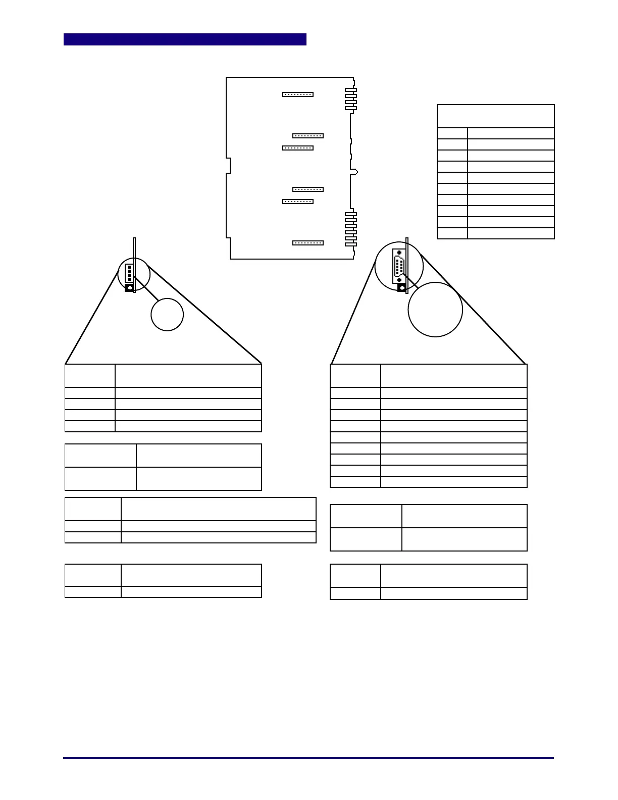
Figure 3. A-60050 Communications Motherboard
P1
P2
P3
P4
P5
P6
P7
P8
P9
P10
POWER SUPPLY
OUTPUTS TO BUS
P1
P2
P3
P4
P5
P6
P7
P8
P9
P10
+5 Vdc Common
+5 Vdc
+5 Vdc Common
+5 Vdc
+5Vdc Common
Not Used
28 Vac ØA
28 Vac ØB
Not Used
Guard
PIN
NUMBER
1
2
3
4
CONNECTOR
(ON CARD)
MATING
CONNECTOR
PIN
NUMBER
CONNECTOR
(ON CARD)
MATING
CONNECTOR
1
2
3
4
5
6
7
8
9
JUMPERS
J1
J2
LEDs
DS1
NO FUSES
J2
J1
P3
P3
NO FUSES (motherboard)
NO JUMPERS (motherboard)
LEDs
DS1
DS1 DS1
A-60062
RS-485 Board
A-60055
RS-232 Board
P3 P3
Data (+)
Data (-)
Common
Shield
E24-1135-004
E24-1134-004
Line Terminator (in for last RS-485 Bd*)
Line Terminator (in for last RS-485 Bd*)
PIN 4
PIN 3
PIN 2
PIN 1
(Viewed as shown - installed )
PIN 5
PIN 4
PIN 3
PIN 2
PIN 1
PIN 9
PIN 8
PIN 7
PIN 6
(Viewed as shown - installed )
Communications Busy
Communications Busy
E24-1118
71-761 (Kit)
DCD (Data Carrier Detect)
RXD (Receive Data)
TXD (Transmit Data)
DTR (Data Transfer Ready)
SGND (Signal Ground)
DSR (Data Set Ready)
RTS (Request to Send)
CTS (Clear to Send)
RI (Ring Indicator)
*As shipped
Slot 3
Slot 2
Slot 1
KEY
Slot 3 is reserved
for RS-485 Daughter Board
Slot 2 may be used
for either RS-232 or RS-485
Slot 1 is reserved
for RS-232 Daughter Board
EPROM 1 EPROM 1
U10
U10
 Loading...
