1640-IN-031-C-08 Page 27 of 104
MACO Series Controller Installation
Eurotherm/Barber-Colman
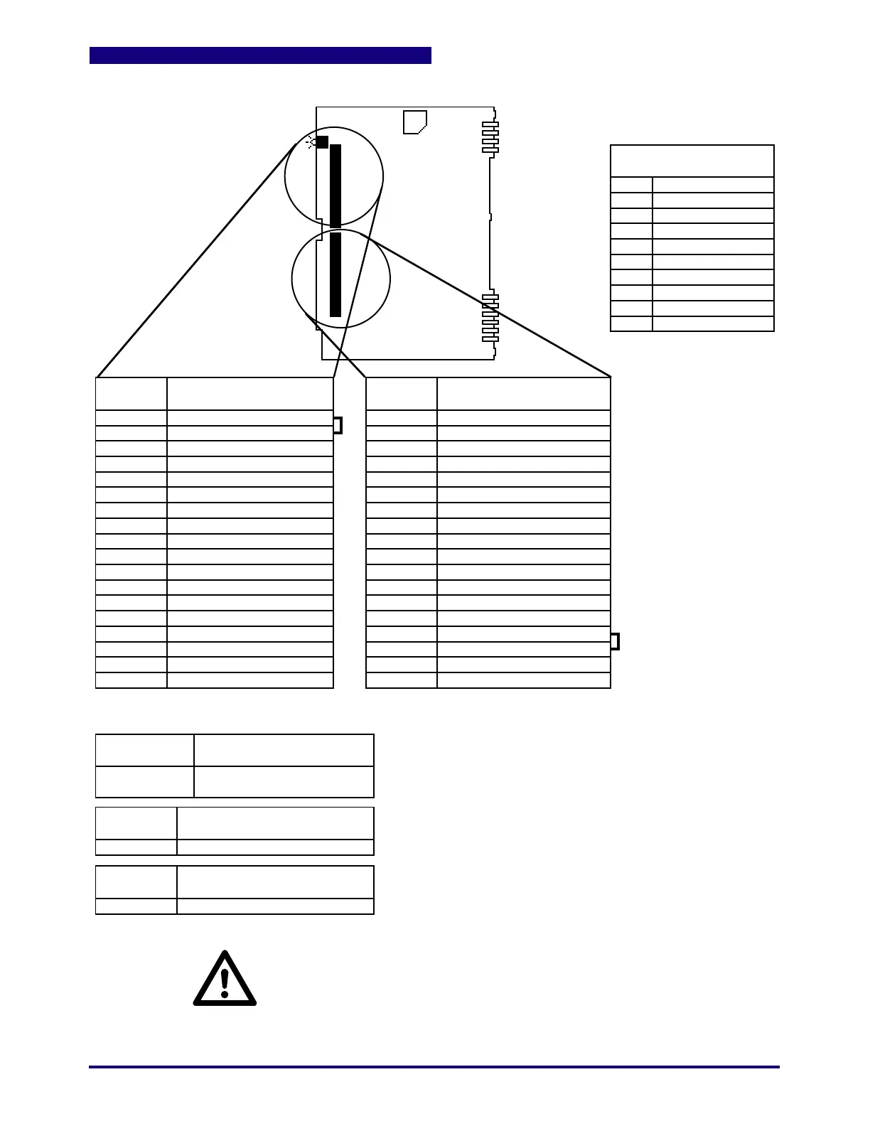
Figure 2.3 A-60063-2XX or A-60133-2XX 6 Zone Analog Input / 6 Zone T/C Input Board
P1
P2
P3
P4
P5
P6
P7
P8
P9
P10
POWER SUPPLY
OUTPUTS TO BUS
P1
P2
P3
P4
P5
P6
P7
P8
P9
P10
PIN
NUMBER
CONNECTOR
(ON CARD)
MATING
CONNECTOR
LED
JUMPER
DS1
J1
1
2
3
4
5
6
7
8
9
10
11
12
13
14
15
16
17
18
(Jumper Pin 1 & 2)
(Jumper Pin 1 & 2)
Zone 1 (-)
Zone 1 (+)
Zone 2 (-)
Zone 2 (+)
Zone 3 (-)
Zone 3 (+)
Zone 4 (-)
Zone 4 (+)
Zone 5 (-)
Zone 5 (+)
Zone 6 (-)
Zone 6 (+)
Not Used
Not Used
Chassis**
Chassis**
Control Fault
Calibrate (Normal Operation*)
E24-1135-018
E24-1134-018
DS1
J1
P14
P14
NO FUSES
*As shipped (for factory use only)
EPROM 1
(U2)
See Cable Assemblies for
Wire Description
P15
P15
PIN
NUMBER
1
2
3
4
5
6
7
8
9
10
11
12
13
14
15
16
17
18
Not Used
Not Used
Zone 1 T/C (-)
Zone 1 T/C (+)
Zone 2 T/C (-)
Zone 2 T/C (+)
Zone 3 T/C (-)
Zone 3 T/C (+)
Zone 4 T/C (-)
Zone 4 T/C (+)
Zone 5 T/C (-)
Zone 5 T/C (+)
Zone 6 T/C (-)
Zone 6 T/C (+)
Balco 2 (Jumper Pin 15 & 16)
Balco 2 (Jumper Pin 15 & 16)
Chassis**
Chassis**
Function A
Zones 1A-6A
Function B
Zones 1B-6B
Note that a wire jumper is
used in place of the Balco
on the terminal block (the
Balcos are located on the
PCB). A Balco failure error
will occur if Balcos are used
on the terminal block.
+5 Vdc Common
+5 Vdc
+5 Vdc Common
+5 Vdc
+5Vdc Common
Not Used
28 Vac ØA
28 Vac ØB
Not Used
Guard
Note also that the wire
jumper remains in place
for analog inputs.
**At the factory, Pin 18 of P14 is connected to Pin 17 of P15 and Pin 18 of P15 is connected to
the EMC bond rail.
WARNING:
Hazardous extraneous voltage capable of causing severe injury or death may exist
between sensor leads and ground. Disconnecting the instrument power may not
remove this voltage. Measure for the presence of voltage between each sensor
lead and ground before servicing. Do NOT place power wiring in the same conduit
or wiring trough with sensor wiring.
C.1
 Loading...
