1640-IN-031-C-08
Page 72 of 104
Eurotherm/Barber-Colman
MACO Series Controller Installation
11. Installing & Wiring Analog Output Boards
Analog output boards have NOT been validated for conformance with the CE EMC
directive. Additional measures beyond those specified here may be needed in
order to demonstrate EMC compliance at the machine level. Proof of EMC
conformance lies with the machine manufacturer.
Note that Analog Output Boards require an external, regulated DC supply capable
of providing 24 Vdc, ±0.5 Vdc with a minimum current of at 0.6 Amps. The power
supply must be CE recognized. The power supply and its ground distribution block
must be located within 30 cm of the bottom of the controller chassis. There must
be NO other (external) devices powered from the supply.
18 gauge wire is recommended as a minimum, but make certain to satisfy all local
and national code requirements.
Sequence card setpoints are used to locate and configure the boards within a rack.
The "First Analog Out Slot" setpoint tells the system which slot contains the first
analog output board:
For 16 Slot Systems:
Count the slot on the far right as "7" and count down from right to left until you count
the analog output card farthest to the left. Enter that number.
For 12 Slot Systems:
Count the slot on the far right as "5" and count down from right to left until you count
the analog output card farthest to the left. Enter that number.
For 7 and 9 Slot Systems:
Enter the number "1"
The "# Analog Output Brds." setpoint tells the system how many (up to 3, except
9 slot systems can have only 1) analog output boards are present in the rack.
The "Analog Brd. 1-3 Out 1-12" setpoints determine the level of each output. An
entry of zero equals 4 mAdc or 0 Vdc. An entry of 32,000 equals 20 mAdc or 10
Vdc, with proportional levels in between.
1.Connect DC + to Pin 1 of P16. Connect DC - to Pin 2 of P16. Pin 3 of P16 must
be connected to directly to earth ground or the earth ground distribution block.
Note: When counting boards in multi-rack
systems (for switch settings, RLD/screen pro-
gramming) count each control rack separately.
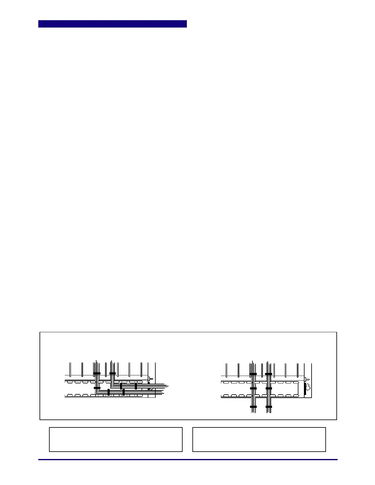
Class 2 Wiring must be separated a minimum of
1/4 inch from any Class 1 conductors.
If both Class 1 and Class 2 Input/Output Boards are present, it may be necessary to bundle wires and
route straight down through the wiring trough in order to meet minimum spacing requirements.
Yes
No
 Loading...
