1640-IN-031-C-08 Page 15 of 104
MACO Series Controller Installation
Eurotherm/Barber-Colman
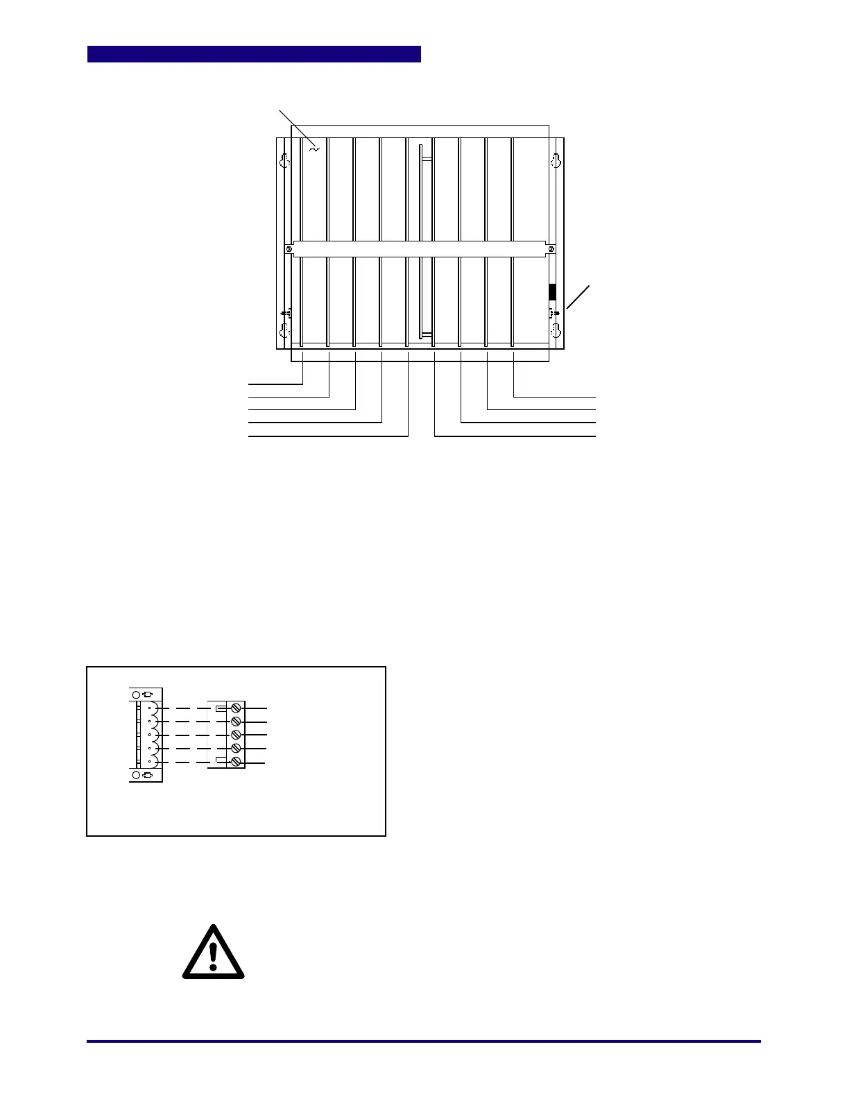
Figure 1.6D 9 Slot Controller Board Locations (3 Slots of I/O)
Note: When counting boards in multi-rack systems (for
switch settings, RLD/screen programming) count each
control rack separately.
Slot #1
Slot #2
Data Handler
Slot #4
Sequence/Hydraulics
Slot #9
Slot #8
Slot #7
Power Supply
Mother Board
Slot 1: Temperature (T/C-Analog)
Slot 2: Temperature, Communications or Analog I/O
Slot 3: Communications or Analog I/O
Slot 4: Data Handler (only)
Slot 5: Sequence/Hydraulics (only)
Slot 6: Power Supply (only)
Slot 7: Input Bd #1
Slot 8: Output Bd #2
Slot 9: Output Bd #1
Energize CR 605
and
Energize CR 607
(if Hi Density I/O)
3 Slots of I/O
See Wiring
Detail Below
CAUTION:
Controller MUST be operated with Cover in place! Wires and Boards carry High
Voltage which may cause Severe Shock or Electrocution. When inserting or
removing Boards, make certain ALL power is OFF. When removing boards, use
card pullers at top and bottom of board. Pull board out approximately 1" and use
insulated screwdriver to "pop" connector free.
B.1
IMPORTANT:
EMC Critical Item
Earth (Safety Ground)
No Connection
L2 Vac IN
No Connection
L1 Vac IN
Top
E24-1261
Viewed from side
of Controller
E24-1134-005
 Loading...
