1640-IN-031-C-08 Page 37 of 104
MACO Series Controller Installation
Eurotherm/Barber-Colman
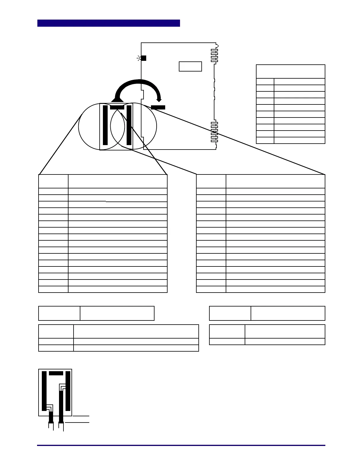
Figure 5.0 A-60051 Analog I/O Motherboard
PIN
NUMBER
1
2
3
4
5
6
7
8
9
10
11
12
13
14
15
16
CONNECTOR
(ON CARD)
P2
P3
P5
P7
P8
P10
P9
P6
P1
P4
PIN
NUMBER
16
15
14
13
12
11
10
9
8
7
6
5
4
3
2
1
P3
P1
P2
P3 P2
CONNECTOR
(ON CARD)
Analog Output #3
Analog Common
Analog Output #4
Shield (open)
Tach Input (15 Vdc max., 1KHz max.)
12 Vdc Common
12 Vdc Regulated (10 mA max. load)
Analog Common
Ejector Position Input /Ana In_3
Ejector Excitation (+)/Ana In_3 EX+
Shield (open)
Shunt Cal Hydraulic 2A/Cal Ana In_4A
Shunt Cal Hydraulic 2B/Cal Ana In_4B
Clamp Hydraulic Input/Ana In_4
Analog Common
Shield (open)
Analog Output #1
Analog Common
Analog Output #2
Shield (open)
Ram Excitation (+)/Ana In_2 EX+
Ram Position Input/Ana In_2
Analog Common
Clamp Position Input/Ana In_1
Clamp Excitation (+)/Ana In_1 EX+
Shield (open)
Shunt Cal Hydraulic 1A/Cal Ana In_5A
Shunt Cal Hydraulic 1B/Cal Ana In_5B
Ram Hydraulic Input/Ana In_5
Analog Common
Shield (open)
Shield (open)
E24-1129-016 E24-1129-016
A-60051A-13637
NO FUSES
LEDs
D28 Control Fault
D28
P1
POWER SUPPLY
OUTPUTS TO BUS
P1
P2
P3
P4
P5
P6
P7
P8
P9
P10
KEY
1/2"
Note: To avoid possible overcrowding of wires, strip cable jacket approximately
1/2" below edge of board and heat shrink leads.
JUMPERS
J1
J2
J1
J2
Board Select (Analog I/O #1* or #2)
Factory Cal (Not in place*)(factory use only)
*As shipped. Note that presently each Analog I/O card requires
its own Seq/Hyd board and ALL Analog I/O's must be set to #1.
EPROM 1
U35
Daughter Board MUST be held in place using 4 screws provided.
Add Cable Ties for strain relief.
See Cable Assemblies for
Wire Description
+5 Vdc Common
+5 Vdc
+5 Vdc Common
+5 Vdc
+5 Vdc Common
Not Used
28 Vac ØA
28 Vac ØB
Not Used
Guard
 Loading...
