1640-IN-031-C-08 Page 11 of 104
MACO Series Controller Installation
Eurotherm/Barber-Colman
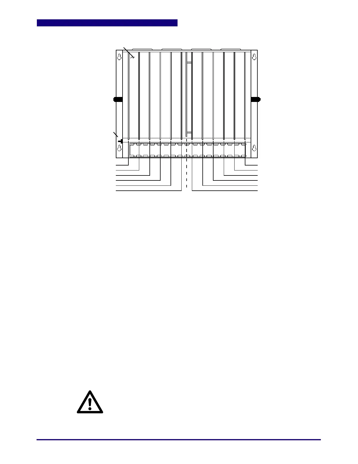
Figure 1.5 12 Slot Controller Board Locations (5 Slots of I/O)
Mother Board
Temperature #1
Slot #2
Slot #3
Data Handler
Slot #5
Sequence/Hydraulics
Slot #12
Slot #11
Slot #10
Slot # 9
Slot # 8
Power Supply
Optional:
Slot #1:
Slot #4:
Slot #5:
Slot #6:
Slot #7:
Temp (T/C-Ana) Bd #1 (or Parison)
Data Handler Bd
Analog I/O
Sequence/Hydraulics Bd
Power Supply Bd (See Note)
Standard:
Slot #2:
Slot #3:
Slot #8:
Slot #9:
Slot #10:
Slot #11:
Slot #12:
Temp (T/C-Ana) Bd #2 (or Parison)
Communications Bd
Output Bd #1
Output Bd #2 or Input Bd #4
Output Bd #3 or Input Bd #3
Output Bd #4 or Input Bd #2
Input Bd #1Note: In 11 or 12-slot controllers, primary power is
connected directly to the power supply board.
Note: When counting boards in multi-rack systems (for
switch settings, RLD/screen programming) count each
control rack separately.
Note: Analog output boards (if used) follow the last
digital output board.
CAUTION:
Controller MUST be operated with Cover in place! Wires and Boards carry High
Voltage which may cause Severe Shock or Electrocution. When inserting or
removing Boards, make certain ALL power is OFF. When removing boards, use
card pullers at top and bottom of board. Pull board out approximately 1" and use
insulated screwdriver to "pop" connector free.
B.1
IMPORTANT:
EMC Critical Item
 Loading...
