1640-IN-031-C-08 Page 79 of 104
MACO Series Controller Installation
Eurotherm/Barber-Colman
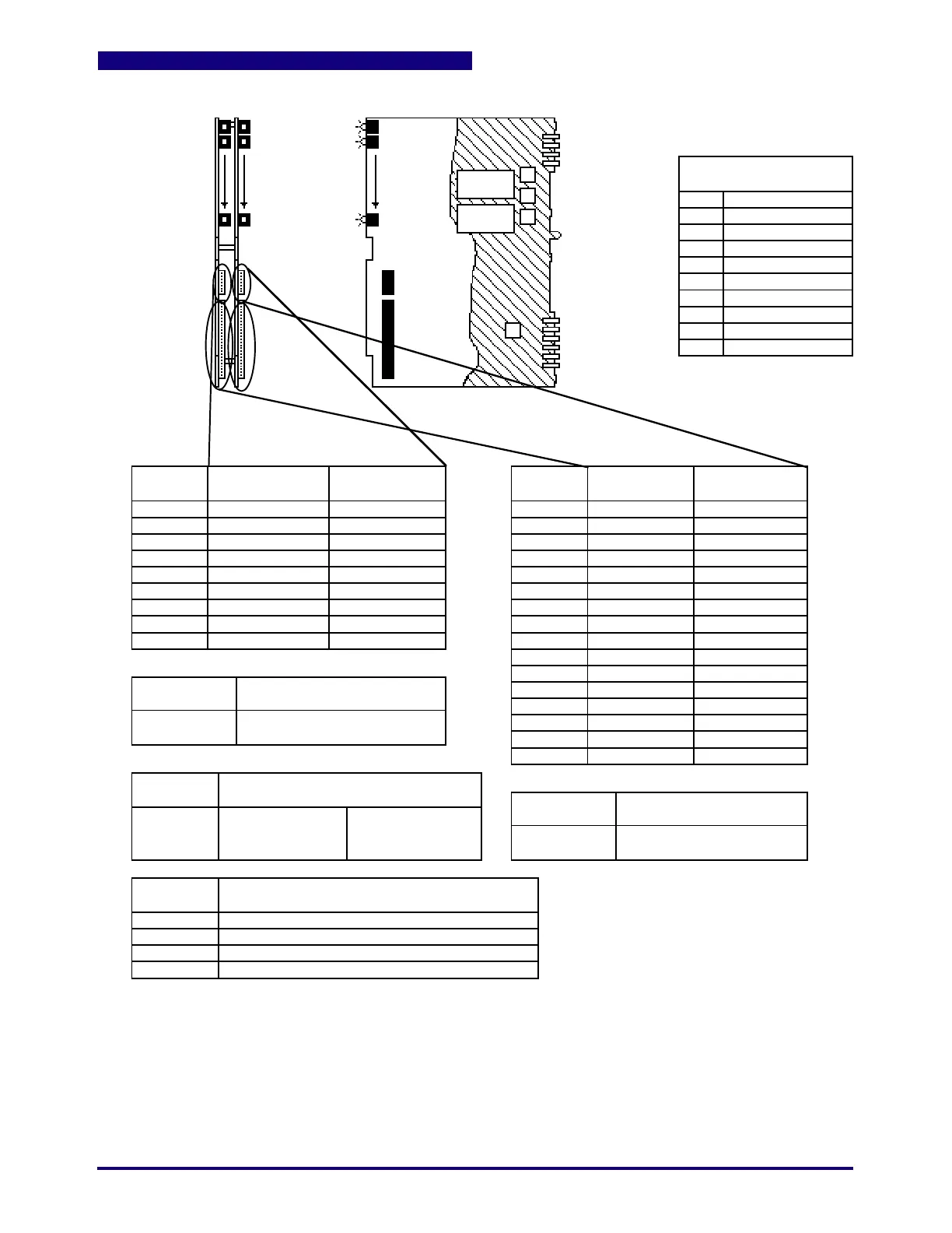
Figure 12.1 High Density AC Input Board Assembly
Note that this assembly may consist of an A-13900 (lower) board and an A-13901 (upper) board
or an A-60089 (lower) board and an A-60090 (upper) board.
P1
P2
P3
P4
P5
P6
P7
P8
P9
P10
POWER SUPPLY
OUTPUTS TO BUS
P1
P2
P3
P4
P5
P6
P7
P8
P9
P10
PIN
NUMBER
CONNECTOR
(ON CARD)
MATING
CONNECTOR
LEDs
DS1
to
DS24
DS1
to
DS24
1
2
3
4
5
6
7
8
9
PIN
NUMBER
1
2
3
4
5
6
7
8
9
10
11
12
13
14
15
16
CONNECTOR
(ON CARD)
MATING
CONNECTOR
L2 (Input 1 - 24)
AC Input 1
AC Input 2
AC Input 3
AC Input 4
AC Input 5
AC Input 6
AC Input 7
AC Input 8
E24-1135-009 (each board)
E24-1134-009 (each board)
E24-1135-016 (each board)
E24-1134-016 (each board)
Input 1
to
Input 24
ON
ON
AC Input 33
ACInput 34
AC Input 35
AC Input 36
AC Input 37
AC Input 38
AC Input 39
AC Input 40
AC Input 41
AC Input 42
AC Input 43
AC Input 44
AC Input 45
AC Input 46
AC Input 47
AC Input 48
P14
P15
P14 P15
NO FUSES
KEY
See Cable Assemblies for
Wire Description
L2 (Input 25 - 48)
AC Input 25
AC Input 26
AC Input 27
AC Input 28
AC Input 29
AC Input 30
AC Input 31
AC Input 32
AC Input 9
AC Input 10
AC Input 11
AC Input 12
AC Input 13
AC Input 14
AC Input 15
AC Input 16
AC Input 17
AC Input 18
AC Input 19
AC Input 20
AC Input 21
AC Input 22
AC Input 23
AC Input 24
DS25
to
DS48
P14
P14
P15
P15
(1 - 24) (25 - 48)
Input 25
to
Input 48
ON
ON
(Lower) (Upper)
(Upper) (Lower)
(Upper) (Upper) (Lower) (Lower)
JUMPERS
1
2
3
4
Position 1 = Low Density; Position 2 = High Density
Position 1 = Low Density; Position 2 = High Density
Position 1 = Low Density; Position 2 = High Density
Position 1 = Low Density; Position 2 = High Density
Check Jumper positions carefully if repositioning!
(on A-13900)
J1
J2
J3
J4
+5 Vdc Common
+5 Vdc
+5 Vdc Common
+5 Vdc
+5 Vdc Common
Not Used
28 Vac ØA
28 Vac ØB
Not Used
Guard
 Loading...
