R5905754 /13 DPxK-32B 75
3. Turn in the three set screws indicated with reference 11 Image 5-30 without disturbing the projected image.
Tighten lightly . Do not turn in the set screw at the lower left of the Lens Holder!
Note: Ensure that the edges of the projected test pattern remain in place on the screen. Any
movement of the image will affect the Scheimpflug adjustment.
4. Fasten the lock nut (reference 21 Image 5-30) of the three set screws. Use a 10mm nut driver. Ensure the
image doesn't move.
Image 5-30
5. Gently turn (by hand) the Scheimpflug adjustment nut at the lower left of the Lens Holder (reference 4
Image 5-31) against the Lens Holder front plate without disturbing the projected image.
6. Turn in the set screw at the lower left of the Lens Holder (reference 14 Image 5-31) without disturbing the
projected image. Use a 3mm Allen wrench.
Note: Ensure that the edges of the projected test pattern remain in place on the screen. Any
movement of the image will affect the Scheimpflug adjustment.
Tip: Fasten the set screw and the Scheimpflug nut alternately, without disturbing the projected image,
until the Scheimpflug nut and set screw are completely tightened.
Image 5-31
7. Fasten the lock nut at the lower left of the Lens Holder. Use a 10mm nut driver.
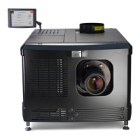
Lenses & lens holder
 Loading...