V5−A/05/14
Instruction Manual w VERTICUS 5 Compressor Units
D-6
- Mount new filter element.
- Mount cover .
3.1.2. IK150, IK15.1, IK15.11, , IK180, IK18.1
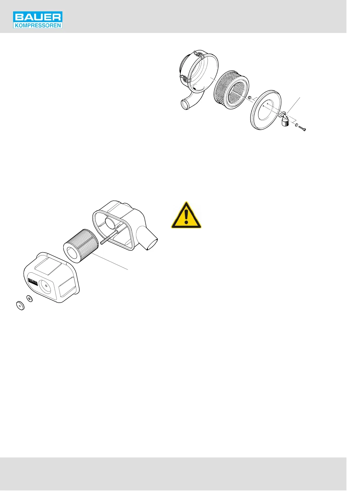
The underpressure in the intake filter is monitored by ser
vice indicator (4, Fig. 109). As soon as the max. allowable
underpressure is reached, indication will change from
green to red. A clogged filter may also lead to shut-down
of the compressor by the min./max. pressure sensors, if
provided! Refer to chapter A.11. In this case change filter
element (2) as follows:
- Open clips and remove cover (3).
- Remove filter element (2).
- Clean the inside of the filter housing with a damp cloth,
take care to prevent any dust entering the intake mani
fold.
- Replace the filter element.
- Mount cover and fasten with the clips.
- Reset vacuum gauge by pressing the button.
Fig. 108 Intake filter, IK12.14
1
Fig. 109 Intake filter, IK150, IK15.1,
IK15.11, , IK180, IK18.1
1
2
3
4
1 Filter housing
2 Filter element
3 Cover
4 Service indicator
4. INTERMEDIATE SEPARATORS
The pressure vessel is subject to dynamic
load. It is designed to withstand a certain
no. of load cycles. (1 load cycle = 1 pres
surization, 1 depressurization) at the spe
cified pressure range. The pressure vessel
must be replaced when the maximum permissible no.
of load cycles has been reached. Refer to the pressure
vessel operating manual delivered with the unit.
4.1. MAINTENANCE
Apart from the regular condensate drain the intermediate
separators are maintenance-free.
4.1.1. Condensate drain
Drain condensate every 15 to 30 minutes from these separ
ators or ensure that the automatic condensate drain unit
drains regularly. See chapter 10.