V5−A/05/14
Instruction Manual w VERTICUS 5 Compressor Units
A-21
10. AUTOMATIC CONDENSATE DRAIN
10.1. COMPRESSOR BLOCKS IK12.14, IK150,
IK15.1, IK180
Description
The automatic condensate drain unit (Fig. 22) drains the in
termediate separators after the 2nd and 3rd stage, and the
final separator after the 4th stage every 15 minutes during
operation.
In addition, the automatic condensate drain is designed to
drain these filters after shut-down of the compressor unit,
and to unload the compressor during the starting phase,
see paras. 10.4. and 10.5.
Fig. 22 Automatic condensate drain unit
1
2
3
4
5
7
6
1 3/2-way solenoid valve
2 Control medium connection
3 Condensate drain valve 2nd stage
4 Condensate drain valve 3rd stage
5 Condensate drain valve, 4th stage
6 Manual condensate drain tap
7 Condensate inlet connection (tube connector)
The automatic condensate drain system operates elec
tropneumatically and comprises the following main items:
Three pneumatically operated condensate drain valves,
one each for the intermediate separators after 2nd and
3rd stage and one for the oil and water separator after
the last stage. The condensate drain valves are of the
normally open type, i.e. they are closed by applying con
trol pressure.
A solenoid valve for control air, normally closed type,
mounted on top of the condensate drain valve for the
2nd stage.
A condensate manifold.
A condensate separator/silencer.
A condensate tank.
A bracket for mounting the drain unit on the com
pressor block or on the unit.
An electrical timer. The timer is mounted in the com
pressor control box on all units fitted with this optional
extra, or in a housing mounted on the unit or delivered
separately with bare compressor blocks.
Operation
The condensate drain valves are operated pneumatically
via a normally closed 3-way solenoid valve by an electrical
signal.
The required control air applied to the solenoid valve is
taken from the intermediate separator after the second
stage.
At compressor start, condensate drain valves (5), (6) and (7)
are open.
At start-up of the compressor, 3/2-way solenoid valve (4) is
energized and opens. Now control pressure is applied to
the condensate drain valves, (5), (6) and (7). The servo-pis
tons (8) are pressed onto valve seats (9) and the condensate
drain valves close.
The compressor delivers compressed medium to the con
nected systems.
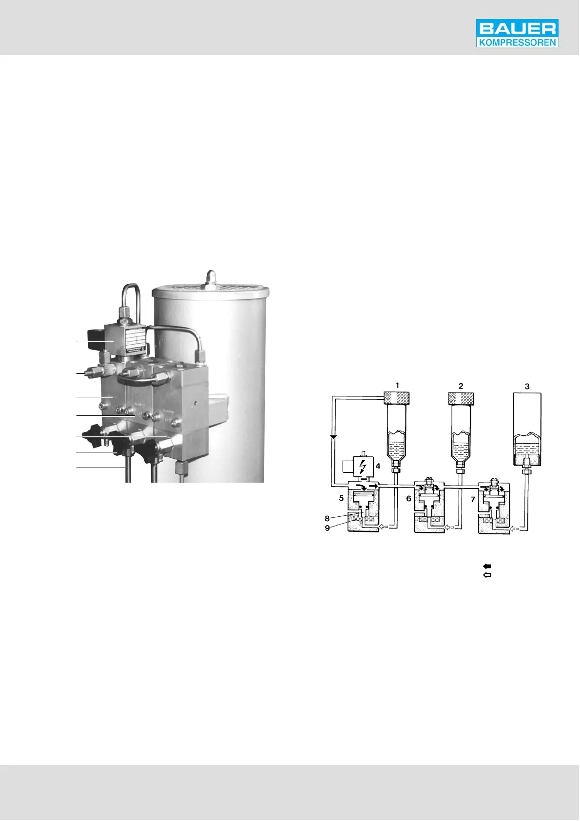
Fig. 23 Normal operation
control pressure
condensate
1 Intermediate separator 2nd/3rd stage
2 Intermediate separator 3rd/4th stage
3 Oil and water separator after 4th stage
4 3/2-way solenoid valve
5 Condensate drain valve 2nd stage
6 Condensate drain valve 3rd stage
7 Condensate drain valve 4th stage
8 Servo piston
9 Valve seat
Condensate drain
Every 15 minutes, 3/2-way solenoid valve (4) is deenergized
for approx. 6 seconds by the timer and closes. The control