V5−A/05/14
Instruction Manual w VERTICUS 5 Compressor Units
A-18
cess by measuring the cartridge saturation within the filter
cartridge.
5.3. OIL AND WATER SEPARATOR
5.3.1. Description
The air leaving the final stage is cooled in the after-cooler
to approx.10 to 15 C (18-27 F) above ambient temperat
ure and then enters the oil and water separator. The oil and
water separator is part of the breathing air purification sys
tem. It separates reliably liquid oil and water particles from
the compressed air.
The oil and water separator is subject to
dynamic load. It is designed to withstand
a certain no. of load cycles. (1 load cycle
= 1 pressurization, 1 depressurization.)
at the specified pressure range. The oil
and water separator must be replaced when the max
imum permissible no. of load cycles has been reached.
Refer to the pressure vessel operating manual de
livered with the unit.
For the lay out of the complete system all components
(compressor, purification, storage cylinders, etc.) are to be
adjusted to each other the best possible way. The number
of starting cycles (4 per hour) must not be exceeded. Actual
running time per cycle should be min. 15 minutes in order
to reach an optimum between utilization ot the unit and
true life time.
The maximum recommended amount of four load cycles
per hour should not be exceeded. If it is possible to regulate
the operation of the unit to such a degree as to achieve four
load cycles per hour, in our opinion this would be an op
timum between usage and actual life.
5.3.2. Purifier
The filter housing consists of an anodized aluminium alloy
pipe with 100 mm external diameter. Both ends are
provided with fine threads on the inside.
The screw-in filter bottom contains inlet and outlet. For
connector threads see specifications, chapter 1.
The upper screw connection contains a pressure resistant
bushing for the electrical connections. The coaxial cable
which leads from the sensor to the control unit is connected
to the BNC connector located there.
5.3.3. Filter cartridges
The cartridge tube is made of aluminium. Cover and bottom
consist of pressure diecast aluminium. The cartridge cover
contains the sensor for the monitoring function and the clip
to facilitate changing of the cartridge.
Different cartridges are available depending on the re
quired air quality.
6. PRESSURE MAINTAINING / NON-
RETURN VALVE
6.1. COMPRESSOR UNITS UP TO 350 BAR
A pressure maintaining and a non-return valve are provided
downstream of the filter system. Refer to flow diagram in
section F. Depending on the model, the combined pressure
maintaining/non-return valve is mounted on the frame of
the compressor unit, or on the outside of the housing. For
the compressor block it is delivered separately.
The pressure maintaining valve ensures that pressure is built
up in the filters even from the start of delivery, thus achiev
ing a constant, optimum filtration. It will also guarantee
proper working conditions for the final stage cylinder.
The pressure maintaining valve is adjusted to 150 10 bar
On units equipped with a filter system, an additional non-re
turn valve is mounted after the oil and water separator -
flanged directly to the filter head. It prevents already
filtered medium from flowing back from the downstream
filters when draining condensate from the oil and water
separator.
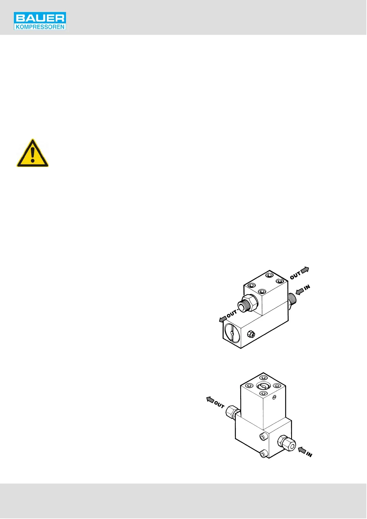
6.2. COMPRESSOR UNITS UP TO 420 BAR
On units with a maximum final pressure of up to 420 bar
(7,250 psi) the pressure maintaining/non-return valve KB
068275 (staninless steel) is mounted.
This pressure maintaining valve is adjusted to 280 10 bar
Fig. 17 Pressure maintaining/non-return valve, 350 bar
Fig. 18 Pressure maintaining/non-return valve, 420 bar