Instruction Manual w VERTICUS 5 Compressor Units
B-6
1.6. ARTIFICIAL VENTILATION
For drive powers above 11 kW natural ventilation may not
be sufficient. Under certain circumstances this can also ap
ply for smaller power ratings, e.g.:
- when locating the compressor in small rooms,
- if ventilation openings cannot be large enough,
- when other systems with high heat radiation are operat
ing in the same room or
- when two or more compressors are operating in the
same room.
The principle is: forced ventilation is obligatory
if room temperature exceeds the allowed ambi
ent temperature stated in the Technical Data
section, A-1.3.
If it is not possible to follow the recommended guide lines
for natural ventilation (e.g. installation of several com
pressor blocks within a very small operating room), the op
erating room must be ventilated artificially.
Cooling air flow
The necessary cooling air flow is calculated to an approxim
ate value by using the following formula:
Required min. cooling air volume [m
3
/h] = 360 x drive
power [kW]
For calculation of the cooling air duct cross section the fol
lowing formula can be used:
Cooling air volume [m
3
/h]
Cooling air flow [m/s] x 3,600
Cooling air duct [m
2
] =
The recommended cooling air flow is approx. 3 to 5 m/s, but
max. 10 m/s.
Example: Verticus 5, drive power 11 kW:
Cooling air volume = 360 x 11 = 3,960 m
3
/h
Cross section = 3960 / (5 x 3,600) = 0.22 m
2
Ventilation methods
There are several types of artificial ventilation:
- Free air flow effected by a blower
- ventilation by means of an air channel with or without
additional blower
a)
- ventilation by means of an air circulating flap with or
without additional blower
a)
If installed correctly, the free air flow cooling method
should be sufficient for all VERTICUS compressor units.
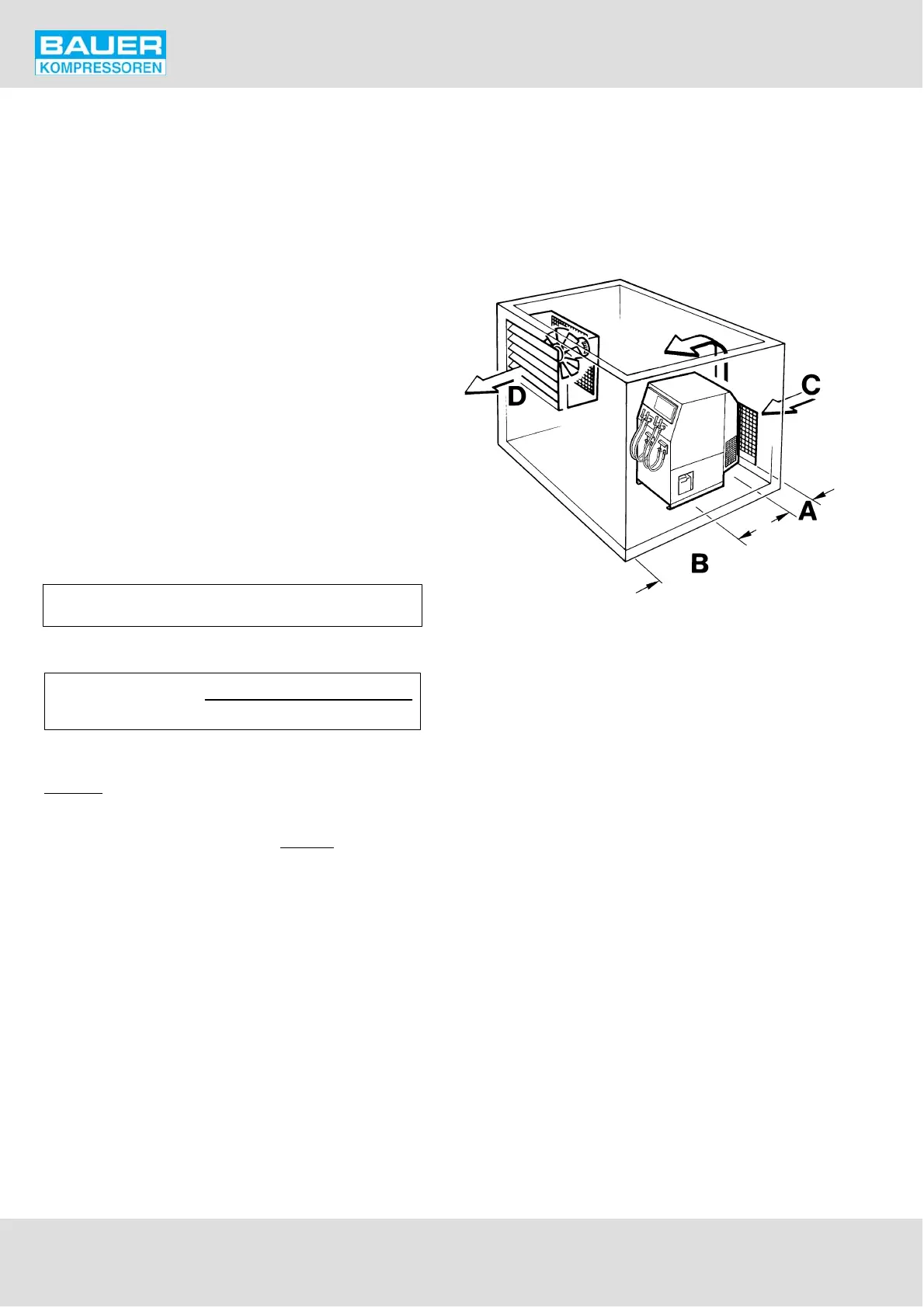
Fig. 91 Installation (artificial ventilation)
A Minimum distance from wall, intake side:
Standard unit: 0.5 m
Super-Silent unit: 0 m
B Minimum distance from wall, exhaust side: 0.75 m (may
be ignored if locating the unit in front of an opening)
C Intake opening
D Exhaust opening
Fig. 92 and Fig. 93 show installation examples with artificial
ventilation:
a) ATTENTION: Ensure that the max. counter-pressure in the intake and outlet channels D
p
= 0.5 mbar = 5 mm W.G. (measured at a
distance of 1 m) is not exceeded.