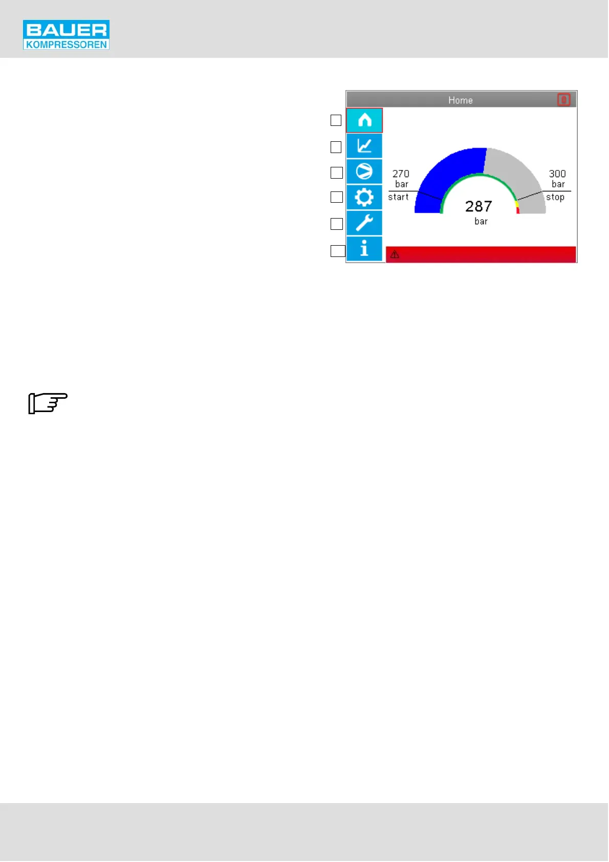
Fig. 36 Operating and display elements
1
2
3
4
5
6
Emergency off pressed
Instruction Manual w VERTICUS 5 Compressor Units
A-30
Control and monitoring elements
The operating panel consists of an LCD colour display and
6 function keys for controlling all functions on the
compressor installation. See Fig. 36. Selection of the func
tion boxes is by using the cursor buttons.
The boxes have the following functions:
1 Main menu
2 Measured values display
3 Compressor Setup
4 B-Control Setup
5 Maintenance
6 Info screen, warning-error messages
General operation:
The selection frame is moved using the cursor buttons via
the function boxes on the display. Each selection is made
using the Enter button. The selection frame is shown by a
red unfilled rectangle having a line thickness of 3 pixels
around the specific selected function box (e.g. in Fig. 36
around Item 1).
If no action is taken after 10 minutes the
display goes back to the start page.