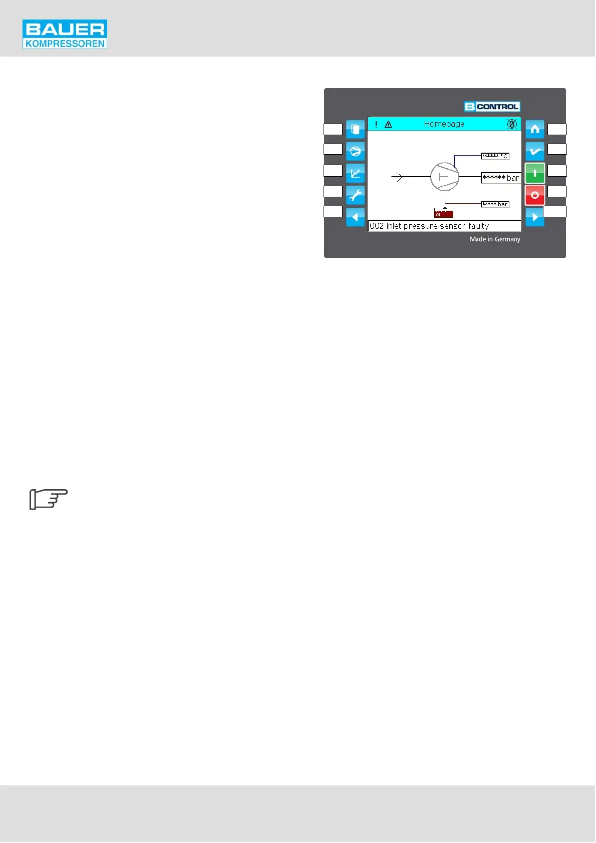
Fig. 39 Operating and display elements
F1 Main menue
F2 Compressor 1 data
F3 Compressor 2 data
F4 Dispenser
F9 Back/ up
F5 Home page
F6 Reset / page back
F7 ON
F8 OFF
F10 Fwd / down
11 Touchscreen display
F1
F2
F3
F4
F9
F5
F6
F7
F8
F10
Instruction Manual w VERTICUS 5 Compressor Units
A-48
11.4.2. HARDWARE AND CONNECTIONS
For reference to the hardware and connections refer to the
schematic diagrams in section F.
For more detailed information about the control system,
refer to the circuit diagramme that comes with the unit.
The configuration of the software with respect to the
hardware is performed in the configuration file. This file is
automatically generated at factory start-up, and normally
does not need any further modification. If a change should
become necessary due to modifications on the compressor
unit, please contact the BAUER after-sales service dept.
11.4.3. Control and Monitoring Elements
The control and monitoring panel features an LCD touch
screen display, 8 soft touch keys and one fwd and one back
key to control the compressor and the display.
The function of the control keys is as follows:
F1 Displays main menue
F2 Displays compressor 1 details
F3 Displays compressor 2 details
F4 Dispenser
F5 Displays home page
F6 Reset / Back to previous page
F7 Compressor ON
F8 Compressor OFF
F9 Back / up in menue
F10 Fwd / down in menue
After 5 min. of no action the display re
turns to the homepage and logs out.