Instruction Manual w VERTICUS 5 Compressor Units
B-7
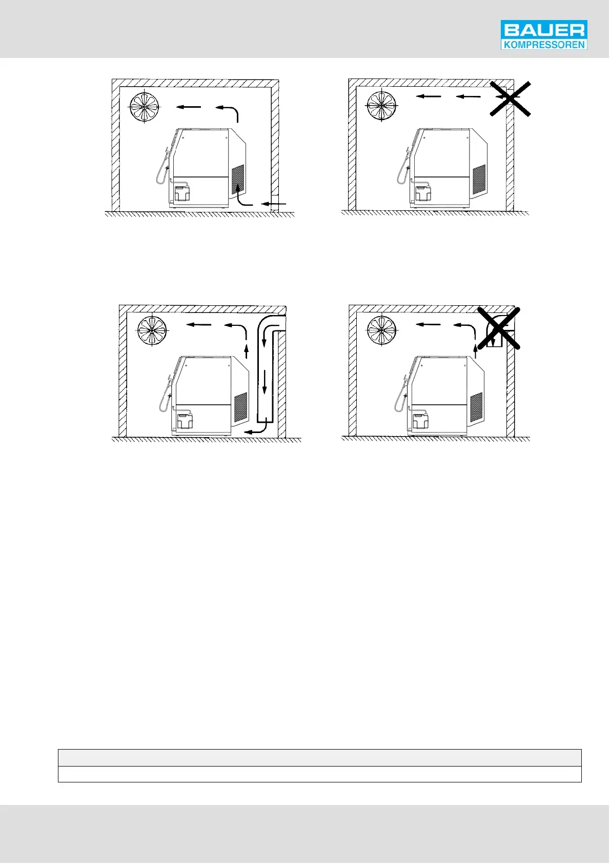
Correct: Air flows along an imaginary
streamline through the compressor
Incorrect: Cooling air does not re
ach unit
Fig. 92 Installation with artificial ventilation, example 1
Correct: cooling air led directly to unit
Incorrect: cooling air duct does not reach
intake opening, intake duct too short
Fig. 93 Installation with artificial ventilation, example 2
2. ELECTRICAL INSTALLATION
For installation of electrical equipment observe the follow
ing:
- In section F. you will find the standard schematic dia
grams valid for the respective compressor unit. To con
nect the compressor control system, use only the dia
gram contained in the control box of the unit, because
any deviations from the standard diagrams according to
order are marked there.
- Observe regulations of local electricity supply company.
- Connection should be carried out by an expert only.
- Ensure correct installation of protective conductor.
- Check conformity of motor and control device tension
and frequency with those of electric network.
- The necessary cabling, main fuse and a main switch
(load-break switch) are to be provided by the customer.
Ensure that the main switch is for one unit only and is
clearly and immediately recognizable. Fusing must be
according to the electricity supply company's regula
tions. For units not connected through a plug, but per
manently installed, a main switch must be provided
which has a contact gap of 3 mm minimum on each
pole.
- Adjust motor protection, thermal overload relay. For
start over contactor adjust to motor amperage rating.
For start via star-delta contactor adjust to motor amper
age rating x 0.58.
For example: motor amperage rating = 10 Amp.:
Adjust relay to 10 x 0.58 = 5.8 Amp.
- Fuse motor correctly (see table below; use slow-blow
fuses, only).
FUSE TABLE
Motor type V 125 230 240 400 415 440 500 600 660
3-phase, 2,2 kW (star-delta starting) A 20 10 10 6 6 6 6 4 4