Instruction Manual w VERTICUS 5 Compressor Units
B-8
3-phase, 2,2 kW (direct starting)
A 25 16 16 10 10 6 6 6 6
3-phase, 3 kW (star-delta starting) A 25 16 16 10 10 10 10 6 4
3-phase, 3 kW (direct starting) A 35 20 20 16 16 10 10 6 6
3-phase, 4 kW (star-delta starting) A 35 20 20 10 -- 10 10 10 6
3-phase, 4 kW (direct starting) A 35 25 25 16 -- 16 16 10 10
3-phase, 5,5 kW (star-delta starting) A 50 25 25 16 16 16 10 10 10
3-phase, 5,5 kW (direct starting) A 63 35 35 20 20 20 16 16 16
3-phase, 7,5 kW (star-delta starting) A 50 35 35 20 16 16 16 16 10
3-phase, 7,5 kW (direct starting) A 63 35 35 25 25 25 20 16 16
3-phase, 11 kW (star-delta starting) A -- 50 50 25 25 25 20 20 16
3-phase, 11 kW (direct starting) A -- 63 50 35 35 35 25 25 25
3-phase, 15 kW (star-delta starting) A -- 63 63 35 35 35 25 25 20
3-phase, 15 kW (direct starting) A -- 80 80 50 35 35 35 35 25
3. CONNECTING EXTERNAL FILLING
PANELS (OPTIONAL)
Breathing air compressor units can be delivered optionally
with separate filling panels. For connection of those ob
serve the following.
Refer to air flow diagram and schematic diagram in section
F. for connecting the filling panel to the compressor unit.
One pneumatic line and, depending on the model, one or
two electrical lines have to be installed on site.
A pneumatic line (stainless steel pipe 8 x 1 mm dia.) con
nects the compressor unit outlet shut-off valve to the in
let connector on the filling panel.
The electric cable from the control box is connected to
the B-CONTROL (S1 and S2, i.e. remote ON an OFF)
The electric cable from the pressure transmitter (-HU
filling panels, i.e. with two pressure ranges, only) is con
nected to the B-CONTROL (F16.2, refer to schematic
diagram).
From the control unit the compressor unit can be switched
ON and OFFl. Failure of the compressor are displayed at the
fault warning lamp and the compressor unit is shut down.
For further information on the B-CONTROL compressor
control, see the instruction manual for the compressor unit
connected.
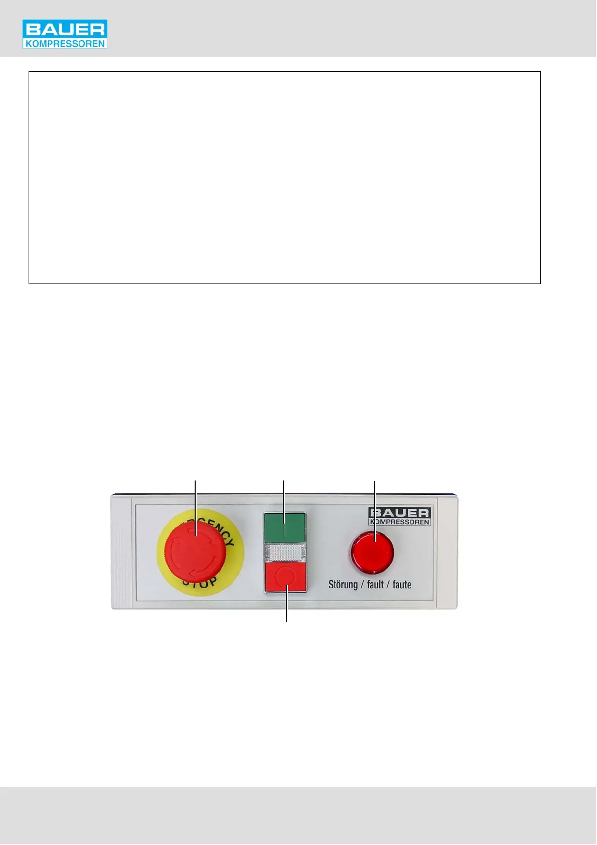
1
4
23
1 Emergency STOP button
2 ON button
3 Fault warning lamp
4 OFF button
Fig. 94 B-CONTROL-Control unit