V5−A/05/14V5−A/05/14
Instruction Manual w VERTICUS 5 Compressor Units
A-66
12. COMPRESSOR DRIVE SYSTEM
As standard, the compressor is driven by the drive motor
through V-belts. Direction of rotation is left, looking at the
cooling fan, i.e. clockwise standing in front of the unit. Ob
serve arrow on compressor.
V-belt tension is adjusted automatically by the weight of the
motor. The motor is mounted on a hinged motor plate.
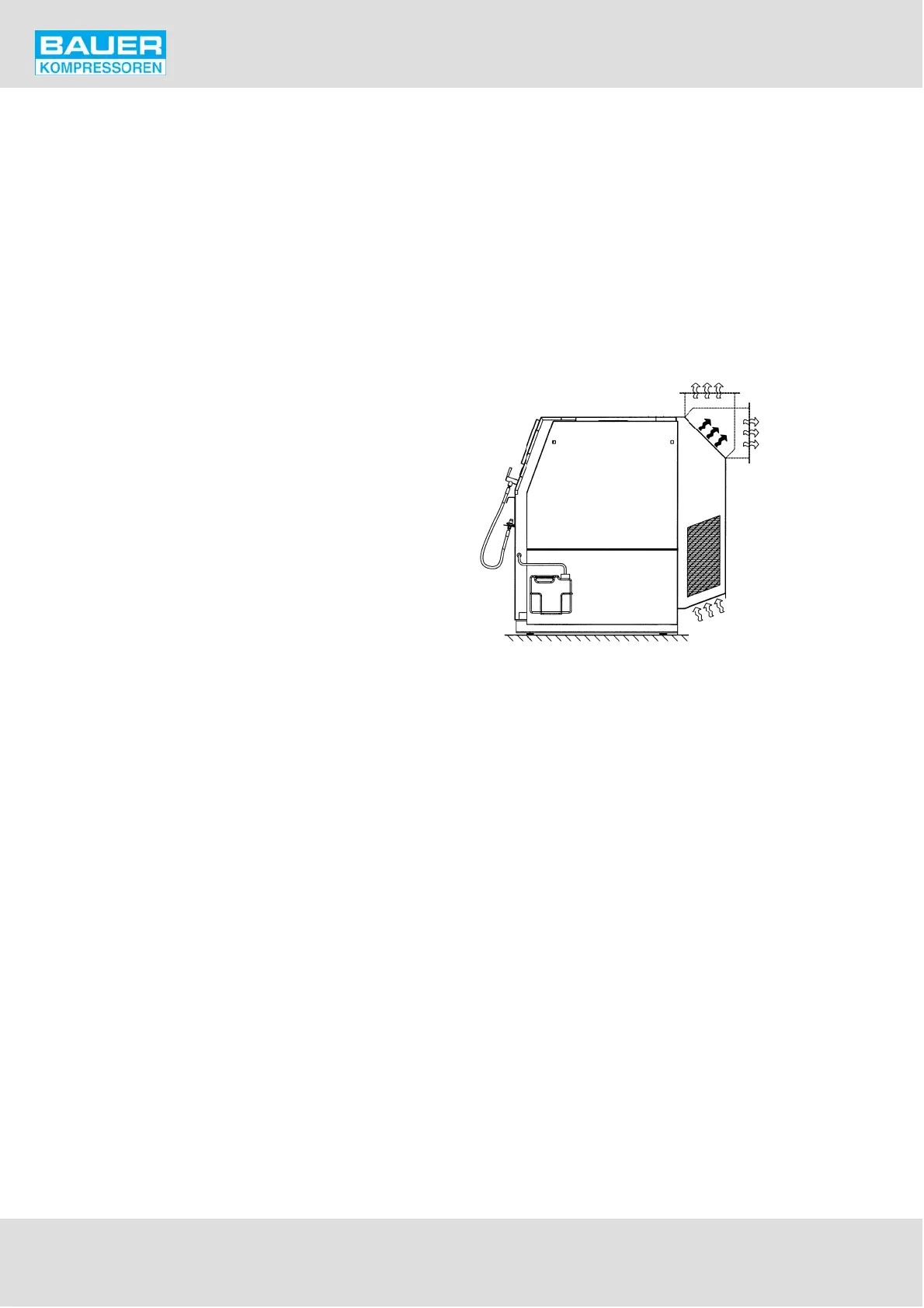
13. COOLING SYSTEM
The cylinders of the compressor block, the intermediate
coolers and the after-cooler are air-cooled. For this pur
pose, the compressor is equipped with a fanwheel which
draws the cooling air through the fanwheel cover from the
surroundings. The fanwheel is driven by the drive motor V-
belt and is also used as the flywheel.
For installation of the unit ensure sufficient cooling air sup
ply. Refer to section B.
For maximum ambient temperature, see Technical Data,
chapter 1.3.
Fig. 84 Cooling air flow
Cooling air inlet
Cooling air outlet
Front
side
optional
optional