Instruction Manual w VERTICUS 5 Compressor Units
A-26
ally switched off by a max. level contact, or an alarm system
provided by the customer can be activated. The separated
air is passed through activated charcoal so that only clean
and odourless air is delivered, in accordance with TRG regu
lations.
The condensate tank is fitted to the condensate outlet con
nector through by hose. The G 3/4” inlet connector is used
for Verticus compressor units.
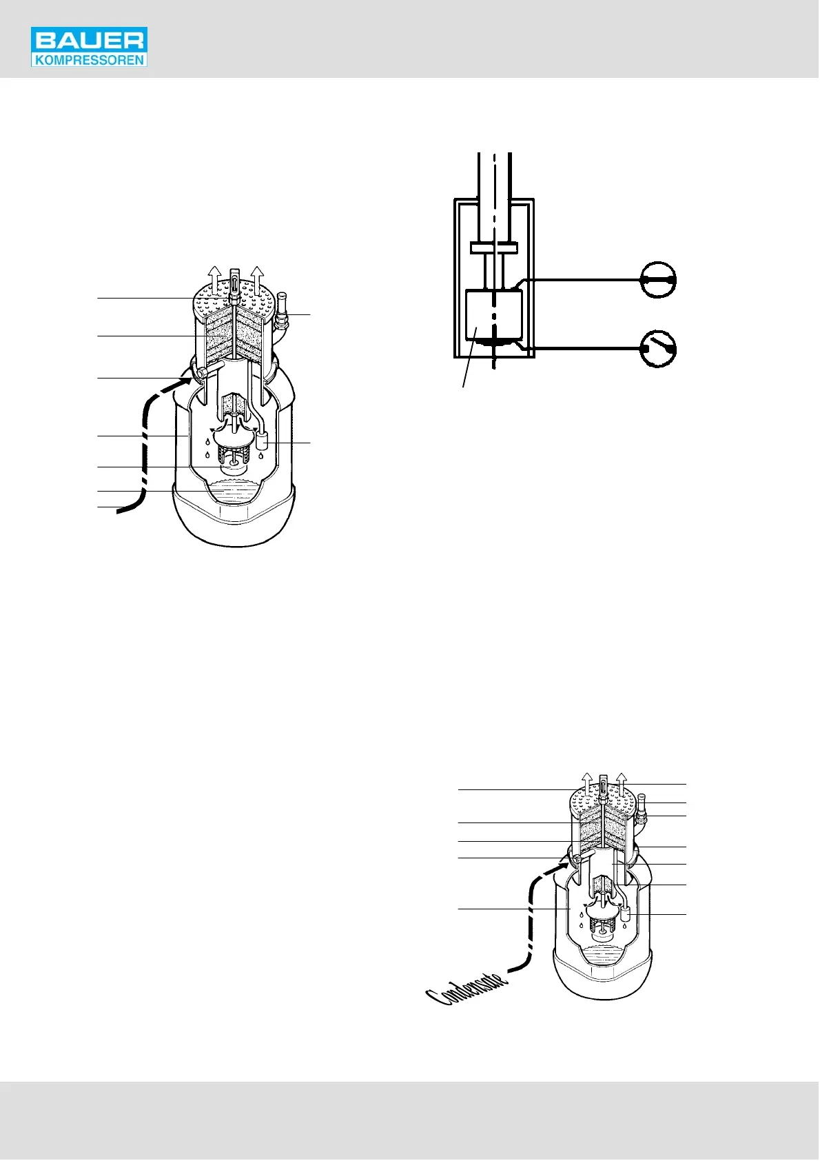
Fig. 32 Condensate collector, 40 ltrs.
1
2
3
4
6
7
5
8
9
1 Level indicator
2 Safety valve
3 Activated charcoal filling
4 Condensate inlet
5 Plastic tank
6 Float
7 Condensate
8 Hose from compressor unit
9 Level switch
Electrical connection
If the BAUER compressor unit is fitted with a compressor
control system including a BC2 electronic monitoring unit,
the level indicator cable must be connected to the BC2 oil
pressure monitoring contact. For all compressor units fitted
with the B-CONTROL compressor control system, the
switch cable is connected to channel 2 of the digital inputs.
Pin 1: signal input
Pin 2: power supply +5 V
When mounting the switch coil (1, Fig. 33), observe the
symbols on the upper and lower switch surfaces. On one
side there is an open switch symbol (3), on the other side a
closed one (2). On all BAUER compressor control systems,
the switch operates with a normally closed contact (empty
container = switch closed). In this case the closed switch
symbol must be on the upper side, see Fig. 33.
Contact function can be changed by mounting the switch
coil upside down.
Fig. 33 Float switch orientation
1
2
3
Function
The condensate is drained by the automatic condensate
drain unit and passed to the outlet connector at the frame.
The hose of the collecting system is connected there.
The condensate enters the system at connector (1, Fig. 34)
and is routed through pipe (2) down into the collecting ves
sel (3). This pipe is filled with steel wool (4). The air entering
together with the condensate, passes through the activ
ated charcoal filling (5) in filter head (6) into the open air.
The charcoal is covered with layers of fleece (7). Tank and
filter head are connected to each other by a clamp (8). The
system is protected by a safety valve (9) if pressure rises
above 0.2 bar for any reason. The condensate level is indic
ated by a sight gauge (11) and monitored electrically by
float switch (10).
Fig. 34 Condensate collector, function
Air
8
7
1
3
5
10
2
4
6
7
11
9