Instruction Manual w VERTICUS 5 Compressor Units
A-11
Compressor blocks IK150,IK180 IK15.1, IK15.11 and
IK18.1
The compressor blocks IK150, IK15.1, and IK180 are
used to compress air in the high pressure ranges PN200 and
PN300 for breathing air application, for industrial applica
tion up to 350 bar (5,000 psi). The max. allowable operating
pressure (adjustment of final pressure safety valve) is 225
bar (3,200 psi) or 330 bar (4,700 psi), respectively for
breathing air units, and 365 bar (5,290 psi) for industrial
units.
Compressor blocks IK15.11 and IK18.1 are used to com
press air in the high pressure range PN420 for breathing air
application, for industrial application up to 500 bar (7,000
psi). The max. allowable operating pressure (adjustment of
final pressure safety valve) is 435 bar (6,300 psi) for breath
ing air units, and 525 bar (7,600 psi) for industrial units.
All compressor blocks except the IK18.1 are of a four stage,
four cylinder design. The four cylinders are arranged at an
angle of 90to each other, 1st and 2nd stage, and 3rd and
4th stage opposite to each other. The 4th stage cylinder is
lubricated by means of the force-feed lubrication system,
the other cylinders are splash-lubricated.
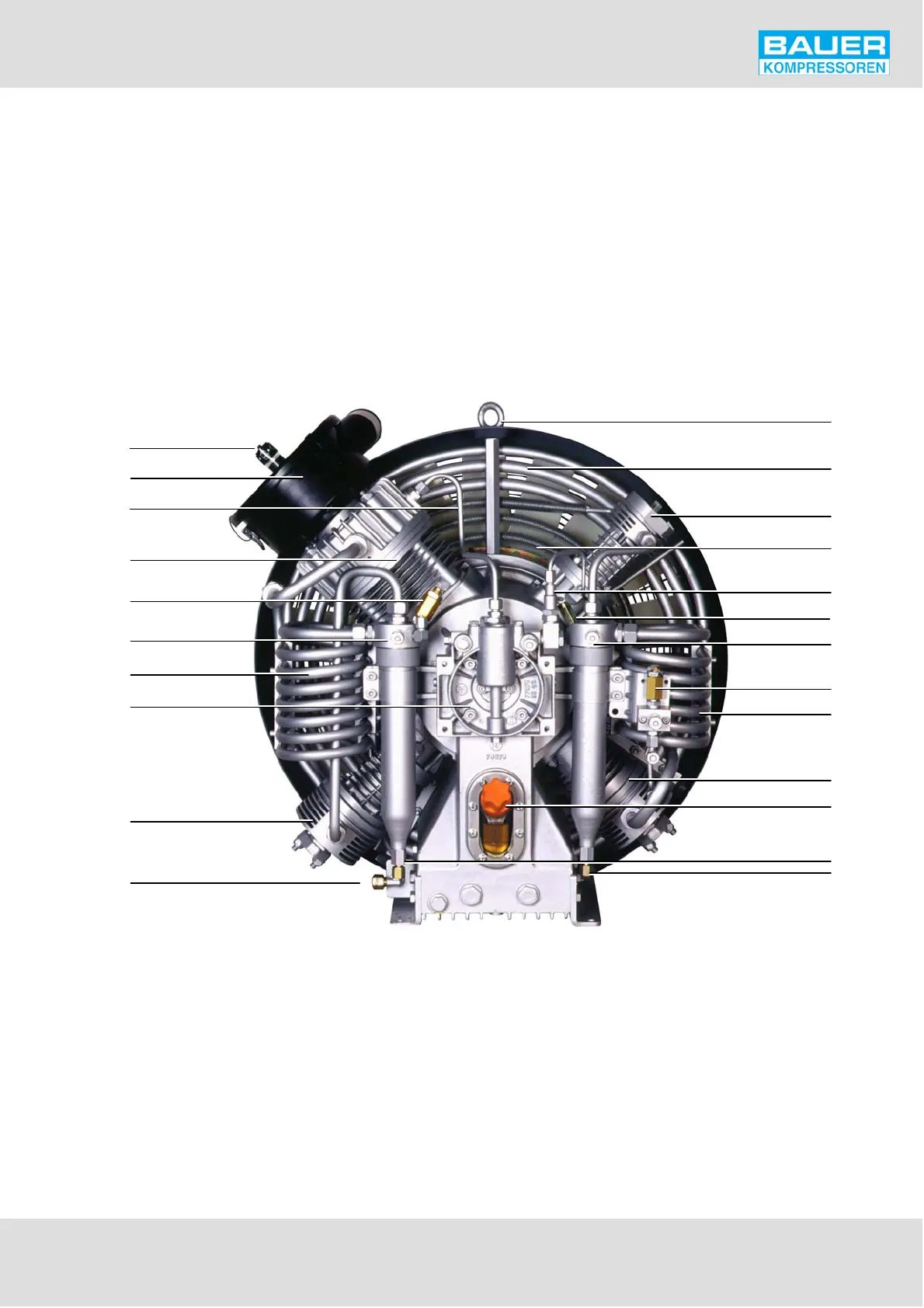
The design of the compressor block is shown in Fig. 8.to
Fig. 11. For the mode of operation refer to the flow diagram
in sec. F.
15
22
12
21
3
1
2
4
7
10
8
9
6
5
16
11
20
18
17
13
19
14
Fig. 8 Compressor block IK150, front view
1 Service indicator
2 Intake filter
3 Crankcase vent feedback line
4 Cylinder, 1st stage
5 Intermediate pressure safety valve, 2nd/3rd stage
6 Intermediate separator, 2nd stage
7 Inter-cooler, 2nd/3rd stage
8 Oil pump housing
9 Cylinder 3rd stage
10 Compressed air outlet
11 Lifting eyebolt
12 Inter-cooler 1st stage
13 Cylinder, 4th stage
14 After-cooler 4th stage
15 Oil pressure regulating valve
16 Intermediate pressure safety valve, 3rd/4th stage
17 Intermediate separator, 3rd stage
18 Intermediate pressure safety valve 1st/2nd stage
19 Inter-cooler 3rd/4th stage
20 Cylinder 2nd stage
21 Oil filler with sight glass
22 Condensate outlet