Instruction Manual w VERTICUS 5 Compressor Units
A-22
pressure is relieved from the servo-pistons (8) of the con
densate drain valves (5), (6) and (7) and the pistons are
raised from the valve seats (9) by the 2nd stage pressure.
The condensate from the separators is drained.
After 6 seconds, the solenoid valve (4) opens again and
opens the control air path from the 2nd stage separator
again. The servo-pistons of the condensate drain valves are
pressed down again and the valves close.
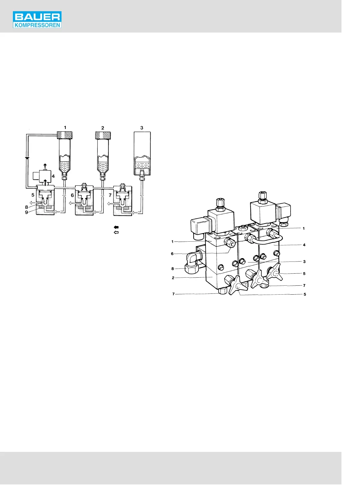
Fig. 24 Condensate drain
control pressure
condensate
1 Intermediate separator 2nd/3rd stage
2 Intermediate separator 3rd/4th stage
3 Oil and water separator after 4th stage
4 3/2-way solenoid valve
5 Condensate drain valve 2nd stage
6 Condensate drain valve 3rd stage
7 Condensate drain valve 4th stage
8 Servo piston
9 Valve seat
10.2. COMPRESSOR BLOCK IK15.11
The automatic condensate drain unit (Fig. 25) drains the in
termediate separators after the 2nd and 3rd stage, and the
oil and water separator after the 4th stage every 15 minutes
during operation.
In addition, the automatic condensate drain is designed to
drain these filters after shut-down of the compressor unit,
and to unload the compressor during the starting phase,
see section 10.4. and 10.5.
The automatic condensate drain system operates elec
tropneumatically and comprises the following main items:
Three pneumatically operated condensate drain valves,
one each for the intermediate separators after 2nd and
3rd stage, and one for the oil and water separator after
the last stage. The condensate drain valves for the inter
mediate separators after the 2nd and 3rd stage are of
the normally open type, the one for the oil and water
separator after the last stage is closed without control
medium being applied (normally closed type).
Two solenoid valves for control medium, normally
closed type, mounted on top of the condensate drain
valves for the 2nd and 4th stage drain valves.
A condensate manifold.
A condensate separator/silencer.
A bracket for mounting the drain unit on the com
pressor block or on the unit.
Two electrical timers. The timers do not operate syn
chronously i.e. 1st, 2nd/3rd and 4th stage are drained
periodically at equal time intervals, but not at the same
time.
Fig. 25 Automatic condensate drain unit
IK15.11
1 3/2 way solenoid valve
2 Condensate drain valve intermediate
separator after 2nd stage
3 Condensate drain valve intermediate
separator after 3rd stage
4 Condensate drain valve oil and
water separator
5 Manual condensate drain valve
6 Control medium connection
7 Condensate inlet
8 Condensate outlet
10.2.1. Operation
All positions refer to Fig. 26.
The condensate drain valves are operated pneumatically
via a normally closed 3-way solenoid valve by an electrical