V5−A/05/14
Instruction Manual w VERTICUS 5 Compressor Units
A-15
2. LUBRICATION SYSTEM
2.1. FUNCTIONAL DESCRIPTION
2.1.1. Compressor Block IK12.14
The compressor is provided with a low pressure lubrication
system. The oil pressure is produced by a low reving gear
pump. The oil pressure is approximately 4.5 bar (3 to 6
bar).
This oil pump will operate in the correct
sense of rotation, only. Otherwise, no oil
pressure will be built up resulting in dam
age of the compressor block.
The oil pump (1, Fig. 12) is coupled to and driven by the
crankshaft. It pumps oil from the oil sump (5) through the
oil fine filter (2) and a minimum pressure valve (3) to the last
stage cylinder. The oil is then distributed by the guide piston
(4) and lubricates all moving parts of the compressor block.
The minimum pressure valve allows for oil pressure indica
tion at a pressure gauge and electronic oil pressure monito
ring.
Fig. 12 Lube oil circuit, IK12.14
1 Oil pump
2 Fine filter
3 Oil pressure regulating valve
4 Cylinder with four stages
5 Oil sump
1
5
2
3
4
2.1.2. Compressor Blocks IK150, IK15.1, IK15.11,
IK180, IK18.1
The compressor is provided with a forced-feed lubrication
(Fig. 13). The oil pressure is produced by a low reving gear
pump. The oil pressure is approximately 4.5 bar (3 to 6
bar).
This oil pump will operate in the correct
sense of rotation, only. Otherwise, no oil
pressure will be built up resulting in dam
age of the compressor block.
The oil pump (1, Fig. 13) is coupled to and driven by the
crankshaft. It pumps oil from the crankcase through an oil
fine filter (2) and a minimum pressure valve (4) to the last
stage cylinder. The oil is then distributed by the guide piston
of the last stage and lubricates all moving parts of the com
pressor block.
The minimum pressure valve allows for oil pressure indica
tion at a pressure gauge and electronic oil pressure monito
ring.
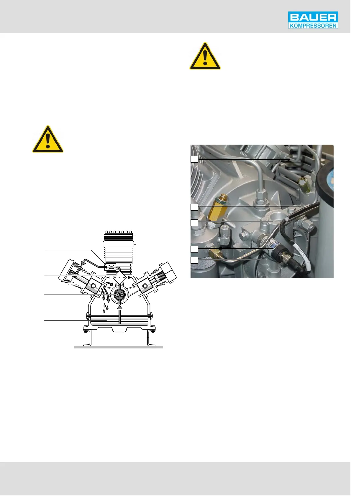
Fig. 13 Lube oil system IK150 to IK18.1
1
2
3
4
5
1 Oil pump housing
2 Oil pressure sensor
3 Oil filter housing
4 Oil pressure regulating valve
5 Injection line to cylinder last stage
2.2. TYPE OF OIL
For proper care and maintenance of the compressor, using
the correct oil is of vital importance. Depending on the ap
plication of the compressor the requirements placed on the
oil are:
low deposits
no carbonizing effect, especially in the valves
good anti-corrosive properties
emulsification of the condensate in the crankcase
for breathing air application, also physiological and tox
icological suitability.
Due to the thermal load on the compressor only high quality
oil should be used. You are recommended to restrict oils to
those which have been approved by us and are listed in our
lubricating oil list.