V5−A/05/14
Instruction Manual w VERTICUS 5 Compressor Units
B-3
B. INSTALLATION, OPERATION
1. INSTALLATION
The compressor frame is isolated with regard to the base
frame of the compressor unit by anti-vibration mounts and
thus a machine base or special means of securing the com
pressor are not necessary.
For installation observe the following:
1.1. COMPRESSOR ROOM CONDITIONS
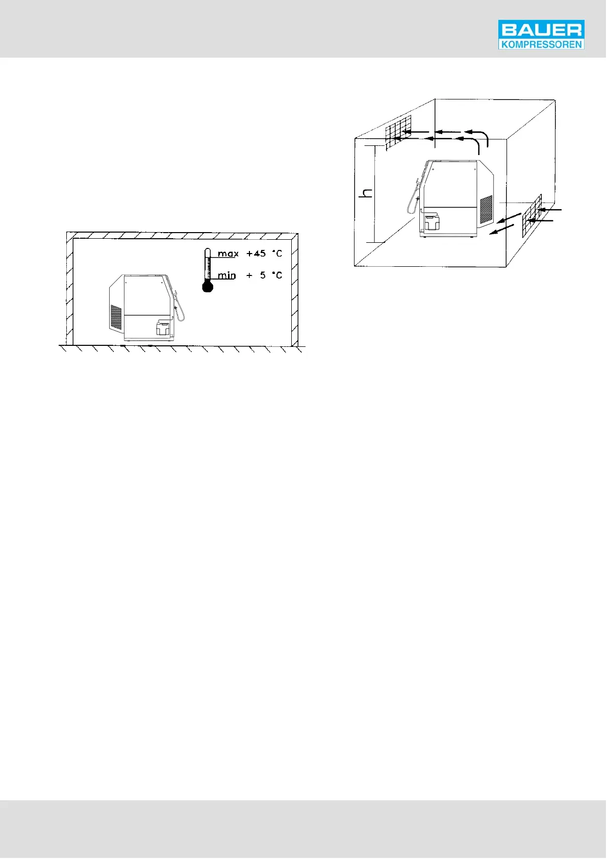
Fig. 85 Room temperature
- The compressor room must be clean, dust-free, dry and
as cool as possible.
- Avoid direct exposure to sunlight; if possible, choose
north side of building.
- Additional heat producing units or line systems should
not be installed in the same room or should be well isol
ated.
- The floor must be capable of taking the load of the sys
tem weight.
- Locate the unit level; refer to technical data for max. al
lowable inclination.
- Ensure adequate ventilation. Remember: room temper
ature = cooling air temperature ! Min. = +5 C, max. =
+45 C. Fig. 85.
1.2. LOCATING THE UNIT
- If possible install unit in such a manner that the com
pressor fan can draw fresh air from outside, for instance
through an opening in the wall as low as possible.
- Ensure that an adequate exhaust air opening is
provided, as high as possible.
- Locate compressor as close to the air intake opening as
possible.
- Locate unit so as to absolutely avoid intake of warm or
hot cooling air.
- Observe the minimum distances as listed in the table
overleaf.
Fig. 86 Locating the unit
1.3. COOLING AIR DUCT INSTALLATION
On all Verticus 5 units the cooling air outlet can be installed
as standard in two different ways. By simply removing the
air outlet cover and grid and mounting them in the desired
position, the air outlet can either be on top or on the back
of the unit (Fig. 84).
If the outlet on the top is selected, the unit can be posi
tioned close to a wall, provided a correct air intake accord
ing to the following paragraphs is ensured.
1.4. AIR BAFFLE CONTROL (Option)
See drawing 073733 in section F, if applicable. The air circu
lating baffles ensure optimal temperature in the com
pressor room or at least that the temperature stays within
the permissible range of +5 to +45C when the outside tem
perature is low.
The recommended controller thermostat setting is +15 to
18C.
Adjustment takes place at 4C above or below the set value.
A temperature sensor in the cooling air intake channel
transmits to the control unit the temperature of the air
taken in. This activates the actuator of the air circulating
baffles. According to requirements, one of the two baffles
in the cooling air exhaust channel is opened. One guides the
warm cooling air to the outside, the other recirculates the
warm cooling air back into the room. The procedure is con
tinuous and therefore the amount of warm air being recir
culated is continually being adjusted as necessary.
The cooling air exhaust channel with baffle unit can be con
nected to the top or the rear of the VERTICUS 5 unit.