Instruction Manual w VERTICUS 5 Compressor Units
A-23
signal. The required control medium applied to the solenoid
valve is taken from the intermediate separator after the
second stage.
Before compressor start-up, condensate drain valves (1)
and (2) are open, (3) is closed by spring pressure.
After start-up of the compressor, i.e. after the star-delta
starter has switched from star to delta phase, 3/2-way
solenoid valve (4) is energized and opens, 3/2-way solenoid
valve (5) is not energized and remains closed. So the control
medium is applied to condensate drain valves (1) and (2),
only. The servo-pistons (6) are pressed onto the valve seats
(7) and the condensate drain valves close.
The condensate drain valve (3) is not pressurized by the con
trol medium. It remains closed by spring pressure and due
to the pressure build-up of the compressor.
The compressor delivers compressed medium to the con
nected systems.
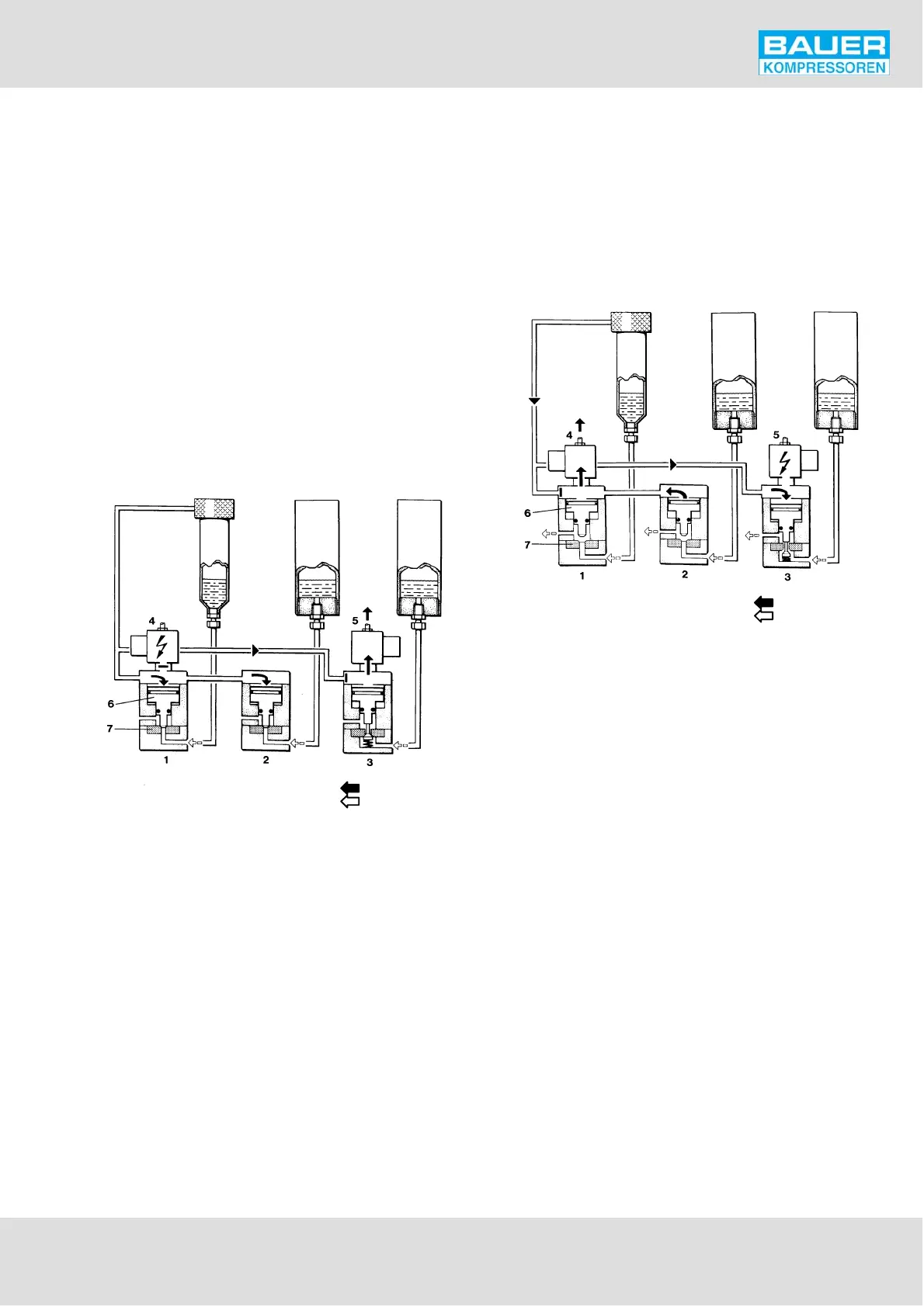
Fig. 26 Normal operation
Control pressure
Condensate
1 Condensate drain valve 2nd stage
2 Condensate drain valve 3rd stage
3 Condensate drain valve 4th stage
4 3/2-way solenoid valve, 2nd/3rd stage
5 3/2-way solenoid valve, 4th stage
6 Servo-piston
7 Valve seat
10.2.2. Condensate drain
All positions stated refer to Fig. 27.
Every 15 minutes, 3/2-way solenoid valve (4) is deenergized
for approx. 6 seconds by the timer and closes. The control
pressure is relieved from the servo-piston (6) of the con
densate drain valves (1) and (2) and the pistons (6) are raised
from the valve seats (7) by the 2nd stage pressure. The con
densate from the intermediate separators after 2nd stage
(1) and 3rd stage (2) are drained.
Also every 15 minutes, but independently from solenoid
valve (4), 3/2-way solenoid valve (5) is energized for approx.
3 seconds by the second timer and opens. The control pres
sure pushes down the servo-piston (6) of the condensate
drain valve (3), the piston is raised from valve seat (7) and
the condensate from the oil and water separator after the
last stage is drained. After 3 seconds the solenoid valve (5)
close again and the control air path is interrupted. The con
densate drain valve (3) is closed by spring pressure.
Fig. 27 Condensate drain
Control pressure
Condensate
10.3. COMPRESSOR BLOCK IK18.1
The automatic condensate drain unit (Fig. 28) drains the in
termediate separators after the 2nd, 3rd and 4th stages
and the oil and water separator after the 5th stage every 15
minutes during operation. In addition, the automatic con
densate drain is designed to drain these separators after
shut-down of the compressor unit, and to unload the com
pressor during the starting phase.
The automatic condensate drain system operates electro-
pneumatically and comprises the following main items:
A 2-way solenoid valve for draining the intermediate se
parator after 2nd stage.
Three drain valves, one each for the intermediate separ
ators after 3rd and 4th stages and one for the oil and
water separator after the 5th stage. The condensate
drain valve for the intermediate separators after the 3rd
and 4th stage are the normally open type and those for
the oil and water separator after the last stage are
closed without control medium being applied.
Two solenoid valves for control medium, normally
closed type, mounted on top of the condensate drain
valves for the 3rd/4th and 5th stage drain valves.
A condensate manifold.
A condensate separator/silencer.
A condensate tank.