V5−A/05/14
Instruction Manual w VERTICUS 5 Compressor Units
A-28
11. ELECTRICAL SYSTEM
11.1. GENERAL
This section describes the standard electric control and
electronic monitoring system of the compressor unit. The
electric control unit is an optional extra for all compressor
units, i.e. the amount of built-in components varies depend
ing on order.
For schematic diagrams, see section F.
The electrical equipment of the compressor unit consists of:
drive motor M1
electric control system
To start the electric motor and enable the functioning of the
controls as well as the monitors, the following components
are essential:
main switch Q1 and
main fuse, both to be installed by the customer.
11.2. EMERGENCY SHUTDOWN
Every unit has an “Emergency Shutdown” push button.
Pressing this push button interrupts the control voltage and
the unit shuts down.
11.3. B-CONTROL MICRO (standard for all
Verticus 5 compressor units)
11.3.1. General
The BAUER B-Control Micro is a freely-programmable
electronic compressor control system. Communication
with the operator is via a colour display and various
different cursor buttons. The compressor control system is
specially programmed for BAUER compressors.
The compressor control system facilitates, among other
things, the display and monitoring of all operationally
relevant parameters, the determination and monitoring of
the maintenance intervals and the recording of all
messages. In addition, the compressor control system
offers three freely-configurable operating modes to be
chosen:
Semi-automatic: the compressor switches off after
manual starting of the compressor when the final
pressure is reached (one pressure value or both pressure
values, depending on the configuration). Automatic
switching on again after the pressure falls below the
switch-on pressure does not take place in this operating
mode.
Fully automatic: after the compressor is started
manually using the ON button, the control system
operates depending on the pressure. If the final pressure
or compressor stop value is exceeded (one pressure or
both pressure values, depending on the configuration)
the compressor switches off. If the pressure falls below
the switch-on pressure or the compressor start value
(interlinked two switch-on values depending on the
configuration), automatic incorporation of the
compressor takes place. This repeats until the
compressor is switched off manually.
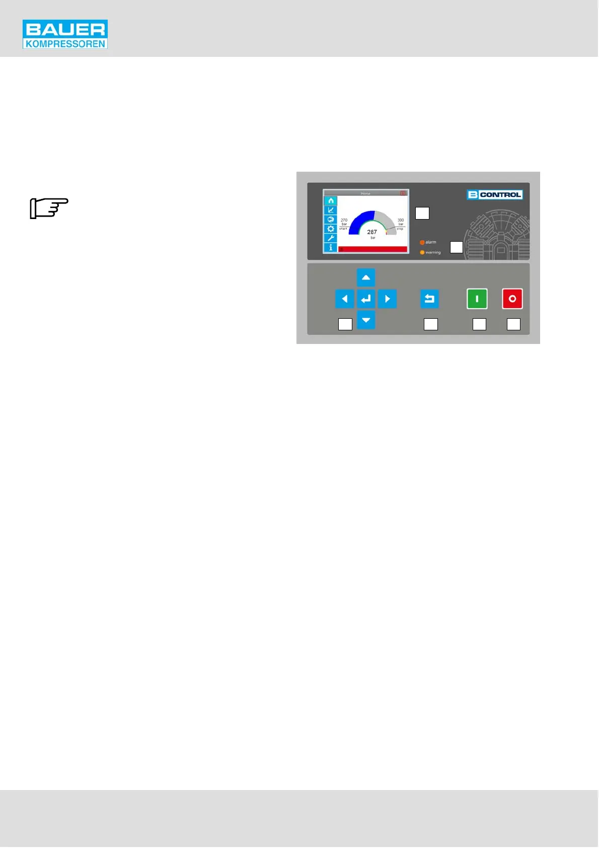
Fig. 35 B-Control Micro
1 2
3
4
56
1 Compressor ON
2 Compressor OFF
3 Filter display
4 Colour display
5 Back button
6 Navigation buttons
Combined operation: the B-Control Micro allows up to
4 compressors to be controlled as slaves in a so-called
combined operation (networked operation). The
master installation requires a B-Control II control
system. A combined operation compressor installation
generally serves to provide increased air demand with
reliability and, to this end, to switch the compressors
OFF and ON, so that the pressure in the target vessel, or
the level in the source (glassblowing) is kept as constant
as possible and to balance the running times of the
compressor as far as possible. The running of
compressors in a combined operation provides
redundancy which ensures compressed air supply in the
event of a fault or when maintenance is being carried
out. The programmed basic/peak load operation makes
sure that the required volume is always provided,
independent of the pressure drop, and that the basic
load is transferred on a time basis from compressor to
compressor. The compressors can either be called up
actively, i.e. via a bus system with appropriately
equipped control system (B-Control Micro or B-Control
extended), or passively by remote on/off contacts. The
control via simple switching contacts also allows the
connection of older compressor installations with
Comp-Tronik control. In order to ensure optimum
function of the combined unit it is necessary to adapt
the operating parameters according to the application
concerned. That is the task of an experienced plant