V5−A/05/14V5−A/05/14
Instruction Manual w VERTICUS 5 Compressor Units
A-16
The current oil list is provided in section
F. Order this list regularly through the
BAUER Technical Service Department.
For operation under difficult conditions such as continuous
running and/or high ambient temperatures we recommend
the use of BAUER high performance compressor oils, only,
according to the oil list. These oils are tested in our com
pressors and have proved excellent quality under ambient
temperatures between +5 C (41 F) and +45 C (113 F).
For lower temperatures, a heating device is required which
is capable of pre-heating the crankcase up to +5 C (41 F).
All our compressor units are delivered ex-
works with lubricating oil N28355.
For operation under less severe conditions we can also re
commend mineral compressor oils which are suitable for
operation under ambient temperatures between +5 C (41
F) and +35 C (95 F). Here also, pre-heating is required for
lower temperatures.
2.2.1. Changing the oil type
To avoid severe damage to the com
pressor unit when changing the oil type,
follow the measures given in section D-2.
3. INTAKE FILTER
3.1. FUNCTIONAL DESCRIPTION
3.1.1. IK12.14
A dry micronic filter is used to filter intake air, see Fig. 14.
It is fitted with a replaceable filter cartridge (1). The intake
pipe is connected to a plastic hose drawing the air from the
cooling air duct.
3.1.2. Intake manifold
As standard, the air is taken in through the cooling air duct
and a plastic hose. Optionally, an intake manifold can be
mounted on top of the unit. This allows the intake air to be
taken from an external source or the surroundings. Refer to
the compressor unit drawing in section F.
Fig. 14 Intake filter, IK12.14
1
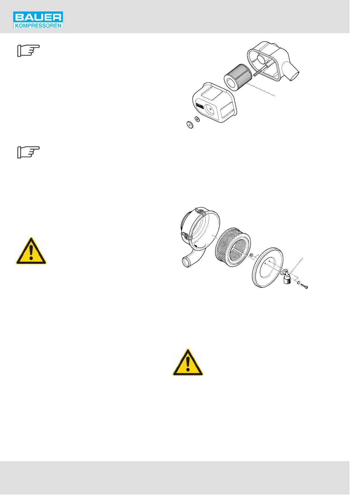
3.1.3. IK150, IK15.1, IK15.11, IK180, IK18.1
A dry micronic filter as shown in Fig. 15 is used to filter in
take air. It is fitted with a replaceable filter cartridge. The
service indicator changes colour from green to red when
the cartridge is clogged.
Fig. 15 Intake filter, IK150, IK180, IK18.1
1 Filter housing
2 Filter element
3 Cover
4 Service indicator
1
2
3
4
4. INTERMEDIATE SEPARATORS
The filter housing is subject to dynamic
load. It is designed for a certain number
of load cycles, which originate from an
abrupt pressure loss at condensate drain
(1 load cycle i.e. condensate drain = 1 de
pressurization, 1 pressurization). The
filter housing has to be inspected in
ternally by an expert after having reached
half of the determined number of load cy
cles. The inspections have to be arranged
by the operator.
The maximum permissible no. of load cycles is written in the
pressure vessel operating manual which is delivered with
each compressor unit.