Instruction Manual w VERTICUS 5 Compressor Units
A-25
pressure build-up of the compressor. The compressor deliv
ers compressed medium to the connected systems.
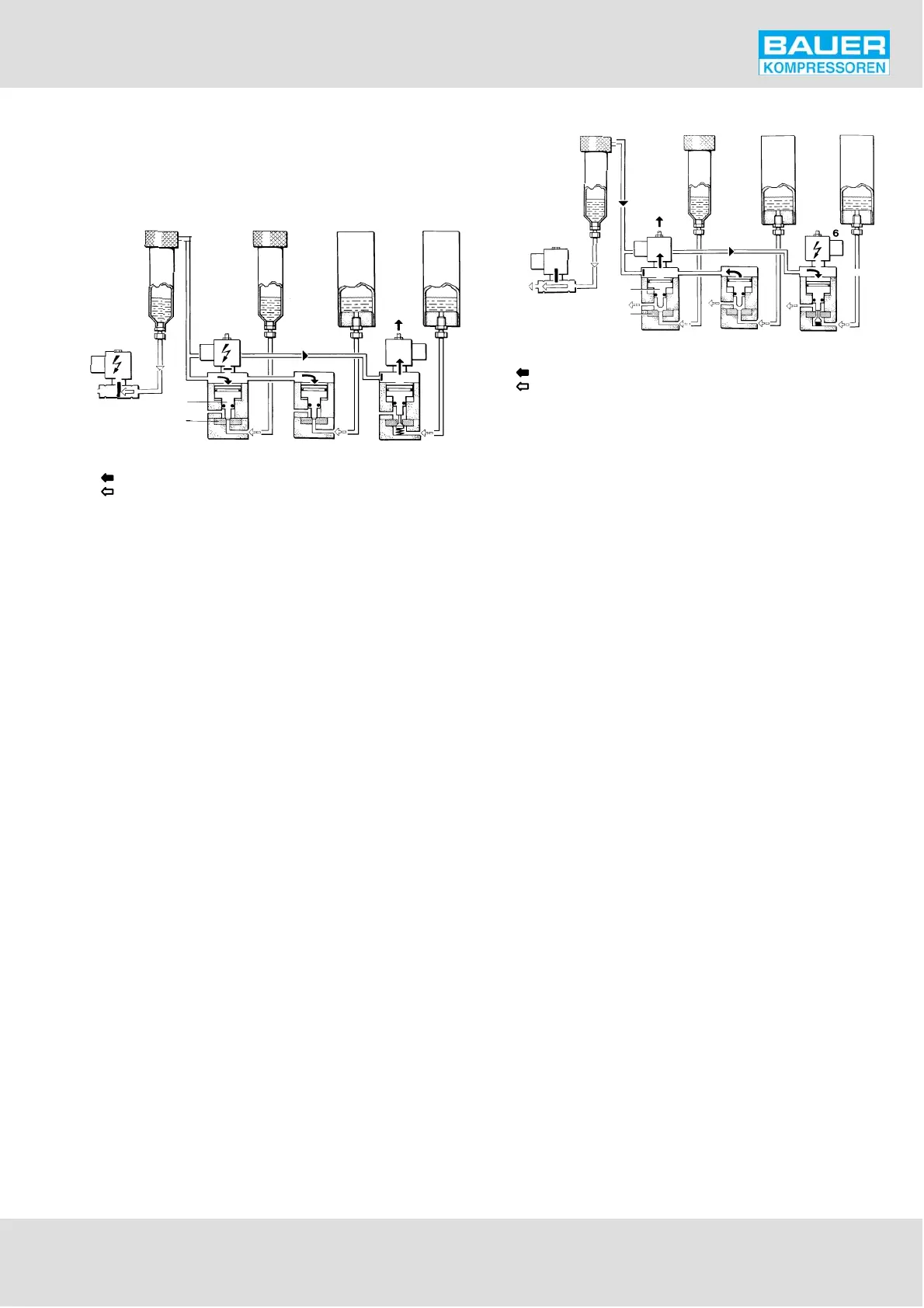
Fig. 30 Normal operation
control pressure
condensate
1
234
56
7
8
1 Condensate drain valve 2nd stage
2 Condensate drain valve 3rd stage
3 Condensate drain valve 4th stage
4 Condensate drain valve 5th stage
5 3/2-way solenoid valve 3rd/4th
stage
6 3/2-way solenoid valve 5th stage
7 Servo piston
8 Valve seat
Condensate drain
Every 15 minutes, 2-way solenoid valve (1) and 3/2-way
solenoid valve (5) are deenergized for approx. 6 seconds by
the timer and close. The control pressure is relieved from
the servo-pistons (7) of the condensate drain valves (2) and
(3) and the pistons are raised from the valve seats (8) by the
2nd stage pressure. The condensate from the intermediate
separators after 2nd, 3rd and 4th stage is drained. After 6
seconds, the solenoid valves are de-energized, and the sys
tem returns to normal operation.
Also every 15 minutes, but independently from solenoid
valves (1) and (5), 3/2-way solenoid valve (6) is energized for
approx. 3 seconds by the timer and opens. The control pres
sure pushes down the servo-pistons of the condensate
drain valve (4), the piston is raised from the valve seat (8)
and the condensate from the oil and water separator after
last stage is drained. After 3 seconds, the solenoid valve (6)
closes again and shuts off the control medium path from
the 2nd stage separator and the valve closes due to spring
pressure. Pressure is built-up from the compressor.
Fig. 31 Condensate drain
control pressure
condensate
1
234
56
7
8
1 Condensate drain valve 2nd stage
2 Condensate drain valve 3rd stage
3 Condensate drain valve 4th stage
4 Condensate drain valve 5th stage
5 3/2-way solenoid valve 3rd/4th
stage
6 3/2-way solenoid valve 5th stage
7 Servo piston
8 Valve seat
10.4. START UNLOADING
The unloading during the starting phase of the compressor
is effected due to the lack of control air/gas immediately
after switching on the unit. After the compressor has at
tained nominal speed, control air/gas flows to the condens
ate drain valves which close and the compressor starts de
livering to the consuming device.
10.5. STANDSTILL DRAINAGE
At compressor shut-down, solenoid valves are deenergized
and open.
The servo pistons are raised by the residual pressure within
the separators. The valves open, and the separators are
drained at standstill of the compressor unit.
10.6. CONDENSATE COLLECTOR 10 ltrs.
BAUER Verticus 5 units are equipped as standard with a 10
liter condensate collector which can be mounted at the
front or the left side as required.
10.7. CONDENSATE COLLECTOR 40 ltrs.
(OPTIONAL)
Optionally, BAUER Verticus 5 units can be fitted with a 40
liter condensate collecting system (Fig. 32). It serves as a
central collector of the accumulated condensate and separ
ates the condensate from the air.
The condensate collecting tank is equipped with a mechan
ical level indicator for optical pre-warning for exchange
when due. In addition, the compressor can be automatic